Cultivator

A cultivator and rack technology, applied in the field of cultivators, can solve the problems of being stuck in a deep quagmire, inconvenient to operate, inconvenient to walk, etc., and achieve the effects of convenient operation, convenient cleaning and simple structure

Inactive Publication Date: 2004-09-01
高名和
View PDF2 Cites 8 Cited by
  • Summary
  • Abstract
  • Description
  • Claims
  • Application Information

AI Technical Summary

Problems solved by technology

However, there are still inconveniences in the operation process, especially

Method used


Image

  • Cultivator
  • Cultivator
  • Cultivator

Examples


Embodiment Construction

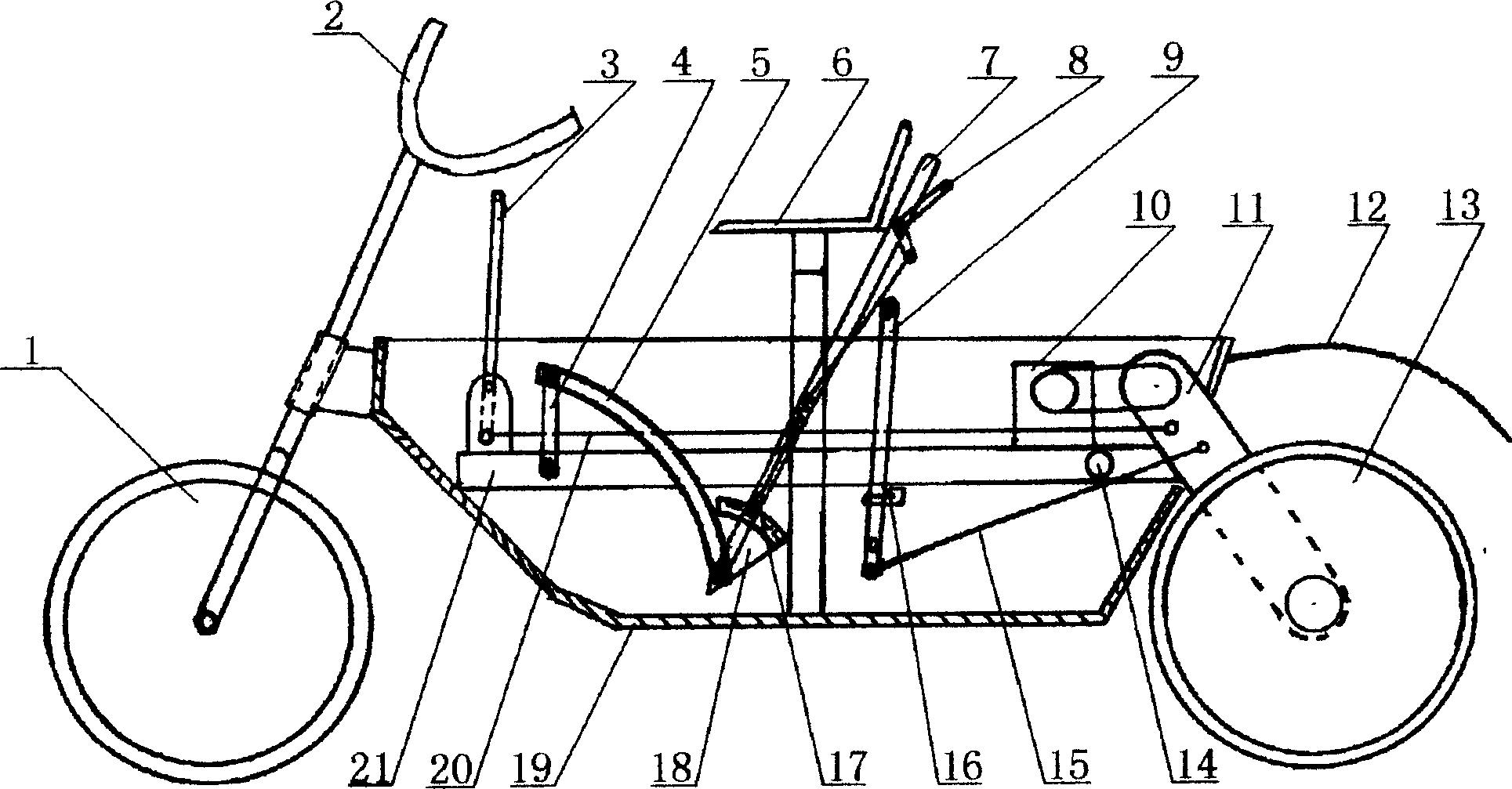
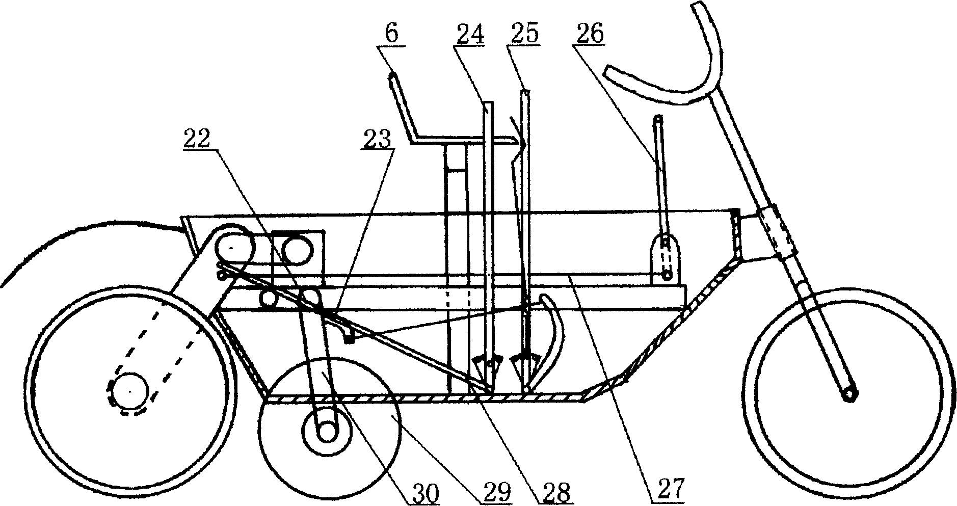
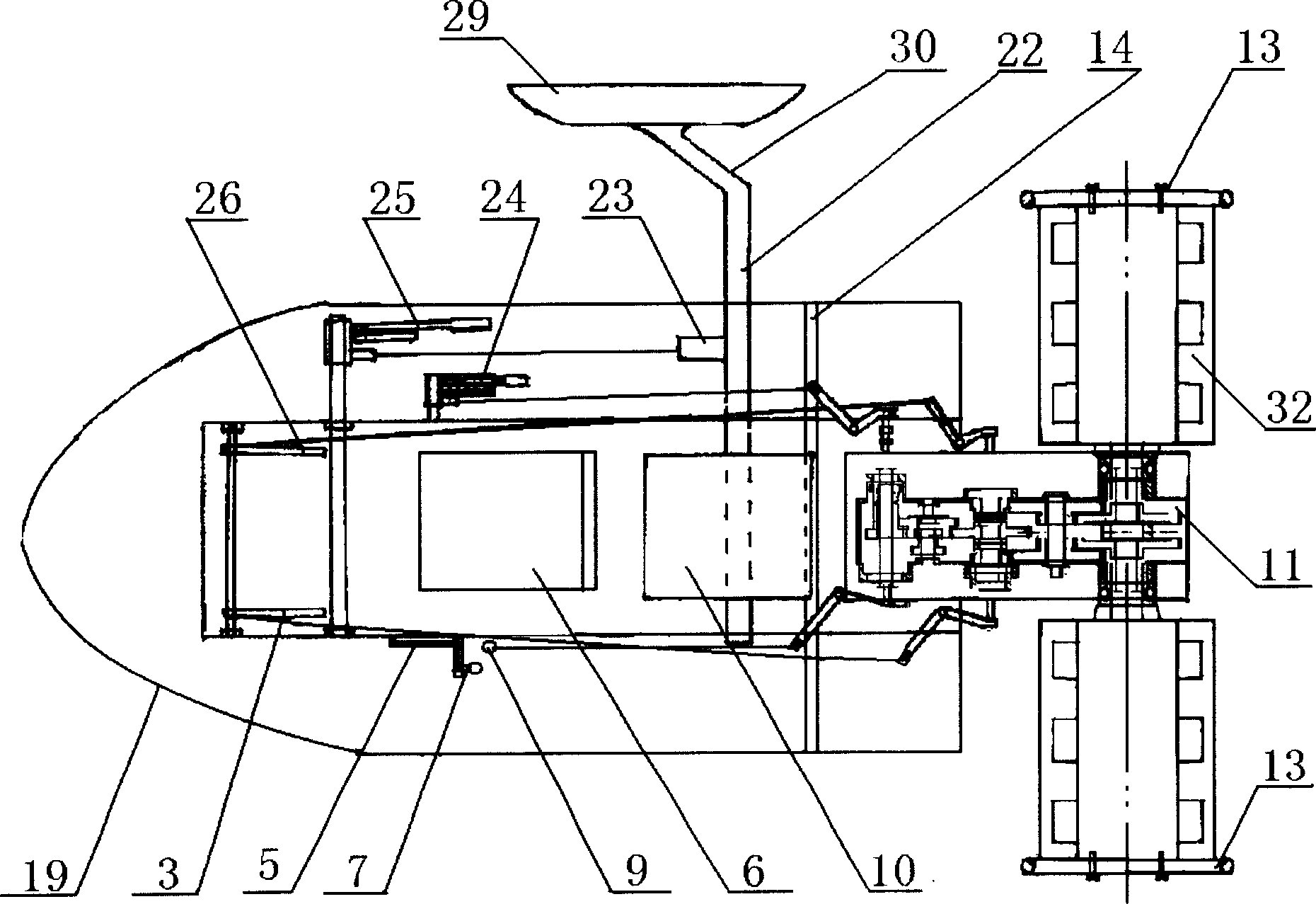
[0015] Depend on Figure 1 to Figure 7 It can be seen that it includes a hull 19, a gearbox 11 installed on the rear end of the hull 19, and rollers 32 that are sleeved on both sides of the gearbox 11 and turn out the shaft. When farming, the power unit drives the rollers 32 through the gearbox 11 to rotate, so that the rollers 32 side volume mud cultivations drive hull 19 to advance or retreat. Frame 21 is hinged with hull 19 by the frame rotating shaft 14 that is installed in hull 19 rear portions, and the lower end of frame boom 4 is hinged with the front portion of frame 21, and the frame boom 4 upper end is with frame boom 5 front ends. Hinged, the other end of the frame boom 5 is affixed to the frame elevating joystick 7 through a rotating shaft or directly. The two ends of the roller body 36 of the fixed roller 32 on the left and right output shafts of the gearbox 11 both sides are enclosed, so that the roller body 36 increases buoyancy and is convenient for cleaning. ...


PUM


Abstract

The invention discloses a cultivator, whose rack assembly is pivoted to the hull through the rack rotation shaft mounted on the rear portion of the hull, wherein the left rotation bar hinged to the rack is connected to the left rotation gear on the tooth sector shaft of the steering link and speed changing box, and the right rotation bar hinged to the rack is connected to the right rotation gear on the tooth sector shaft of the steering link and speed changing box, the clutch lever hinged to the hull is connected to a clutch sleeve shaft of the speed changing box through the connecting link of the clutch, the shift control lever pivoted on the hull is connected to the shift control shaft of the arm and power arrangement. The invention realizes simple structure, small volume and convenient operation. íí

Description

Technical field [0001] The invention relates to an agricultural machine, in particular to a tiller suitable for paddy field farming. Background technique [0002] At present, the machinery used for paddy field farming generally adopts the form of machine-rolling boat or plow type. Such machinery is inconvenient to operate, or the structure is too complicated, the cost is too high, or the structure is too simple, and it is not practical or durable. It is difficult to work on cultivated field corners and small fields. I applied for a patent on May 31, 2000, "a lifting plow for a tiller" (patent application number: 00224926.X, publication date: 2001.09.05, publication number: 2445553), which discloses a The lifting plow used for cultivating machines, one end of the lifting seat fixed with the lifting rack is hinged to the hinge support, the other end is fixed to the traction arm on which the plow is installed, and the lifting rack is set on the upper end of the hinge support. ...

Claims


Application Information

Patent Timeline
IPC IPC(8): A01B51/02
Inventor 高名和
Owner 高名和
Why Eureka
Try Eureka