A unit for adjusting clamping force for a vice

A technology for adjusting devices and clamping force, which is applied in vices, positioning devices, transmission devices, etc., and can solve problems such as damage to workpieces, large losses, and reduced processing accuracy.

Inactive Publication Date: 2004-09-01
SAMCHULLY MASCH CO LTD
View PDF0 Cites 6 Cited by
  • Summary
  • Abstract
  • Description
  • Claims
  • Application Information

AI Technical Summary

Problems solved by technology

[0004] However, in the vise with the former hydraulic force applying device, when a large external force is applied to the workpiece clamped between the fixed jaw and the movable jaw, due to the above hydraulic force applying device will produce Instantaneous pressure drop, it is easy to shift the position of the workpiece, and the workpiece will fall off
In particular, in the case of precise machining of workpieces, there are disadvantages such as damage to the workpiece or reduction in machining accuracy due to shifting or falling off of the workpiece position.
[0005] In the latter vise with a mechanical force applying device, when a large external force is applied to the workpiece, although it can prevent the momentary pressure drop of the force applying device, since each movable roller is in sliding contact Moving, the loss caused by friction is large, and therefore has the disadvantage of low efficiency relative to the clamping force generated by the applied external force
[0006] In addition, when the vise with a force-applying device is operated with excessive force in order to firmly clamp the workpiece, the clamping force of the movable jaw on the fixed jaw will be too large, and the workpiece will be deformed, or Adverse consequences such as damage to the workpiece

Method used


Image

  • A unit for adjusting clamping force for a vice
  • A unit for adjusting clamping force for a vice
  • A unit for adjusting clamping force for a vice

Examples


no. 1 example

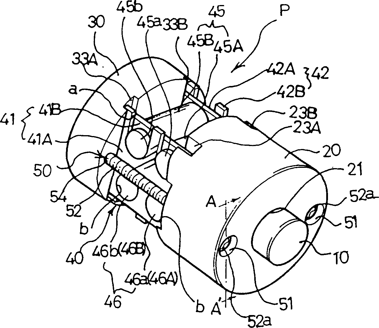
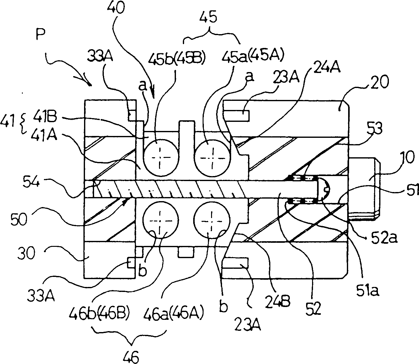
[0033] The force applying device P of the first embodiment is generally as Figure 2 ~ Figure 4 As shown, it is composed of a first moving part 10 , a holding part 20 , a second moving part 30 , a force part 40 and a clamping device 50 .

[0034] The first moving part 10 is in the shape of a round rod, and its front end forms a sharp wedge shape (conical shape in this embodiment) forming an acute angle.

[0035] The holding member 20 is substantially cylindrical, and a shaft hole 21 is formed at the center thereof through which the first moving member 10 can pass and can move back and forth freely. In addition, on one end surface of the above-mentioned holding member 20, there are formed first and second guide grooves 23A, 23B which are symmetrical to the diameter and are respectively parallel to the diameter with any one diameter passing through the shaft hole 21 as the center line. Between the two first guide grooves 23A and the second guide grooves 23B, flat first and seco...

no. 2 example

[0061] Below, refer to Figure 6 A second embodiment of the urging device P of the present invention will be described.

[0062] The urging device P of the second embodiment, except that no inclined surface is formed on the holding member 20 contacting the front upper roller 45A and the front lower roller 46A, only moves in the second contact with the rear upper roller 45B and the rear lower roller 46B. Except that the inclined surfaces 34A, 34B are formed on the member 30, other configurations are the same as those of the urging device P of the first embodiment. Therefore, the same components as those in the first embodiment are assigned the same reference numerals, and description thereof will be omitted.

[0063] Such as Figure 6 As shown, in the second embodiment, the holding part 20 is roughly cylindrical, and a shaft hole 21 through which the first moving part 10 passes and can move back and forth freely is formed in the center. Any one of the diameters passing throu...

no. 3 example

[0066] Below, refer to Figure 7 A third embodiment of the urging device P of the present invention will be described.

[0067] In the urging device P of the third embodiment, the inclined surfaces 24A, 24B and the inclined surfaces 34A, 34A, Except for 34B, other constitutions are the same as those of the urging device P of the first and second embodiments. Therefore, the same components as those in the first and second embodiments are assigned the same reference numerals, and description thereof will be omitted.

[0068] Such as Figure 7 As shown, in the third embodiment, the holding part 20 forms a shaft hole 21 in the center that allows the first moving part 10 to pass through and move back and forth freely. Any diameter of the hole 21 is used as the center line, and the first and second guide grooves 23A, 23B parallel to the above-mentioned diameters are formed respectively between the above-mentioned first guide groove 23A and the second guide groove 23B from the abo...


PUM


Abstract

The present invention provides a unit for increasing clamping force for a vice which holds an object on a machine tool in position and to a unit for adjusting clamping force directed from a movable jaw of the vice to a fixed jaw thereof. The unit for increasing clamping force (P) comprises a first moving member (10), a holding member (20), a second moving member (30), a unit for increasing force (40) and a pair of connecting means (50). In addition, the unit for adjusting clamping force (C) comprises a coupling part (110), an interval maintaining part (120), a central axis (130), a first clutch (140), an adjusting knob (150), a second clutch (160) and a guide axis (170).

Description

technical field [0001] The present invention relates to a force applying device for fixing (clamping) a workpiece in a vise on a machine tool, increasing the clamping force from the movable jaw to the fixed jaw, and the above force applying device can be easily adjusted The clamping force adjustment device of the clamping force. Background technique [0002] Conventionally, as a vise with a force applying device, a vise having a hydraulic type force applying device has been used (for example, Japanese Patent Publication No. 46-15400 and Japanese Patent Publication No. 63-41711, etc.). Most of these vises are composed of the following components: a chassis fixed on the workbench of the machine tool; a fixed jaw fixed on the chassis; a movable jaw that can slide freely on the chassis ; A tubular screw that is installed on the bottom frame and can rotate and slide, is connected with the movable jaw by threads, and can move the movable jaw; passes through the central hole of th...

Claims


Application Information

Patent Timeline
Patent Type & Authority Applications(China)
IPC IPC(8): B23Q3/06B25B1/02B25B1/10F16H25/18
CPCB25B1/106F16H25/183B25B1/103B25B1/02
Inventor 徐洪锡
Owner SAMCHULLY MASCH CO LTD
Why Eureka
Try Eureka