
Magnetic head, magnetic head apparatus and shielded enclosure

A technology of shielding cover and magnetic head, which is applied to the housing/shielding cover of the recording head, the manufacture of magnetic heads with a structure composed of multiple magnetic heads, and magnetic recording heads. question

Inactive Publication Date: 2004-09-01
ALPS ALPINE CO LTD
View PDF1 Cites 0 Cited by
  • Summary
  • Abstract
  • Description
  • Claims
  • Application Information

AI Technical Summary

Problems solved by technology

[0014] However, if this method is used, since it is necessary to set the height positioning by estimating the deviation of the above-mentioned magnetic head structure, it is necessary to prepare additional tools corresponding to the size of the deviation, and it is necessary to grasp the degree of manufacturing deviation of the magnetic head, etc., so it is necessary to increase the number of working procedures and tools. In addition, there is also the problem that the positional accuracy of the magnetic core halves 100, 101 inside the shield 105 cannot be improved according to the occurrence or size of the deviation.
[0015] In addition, with regard to the structure disclosed in the above-mentioned Japanese Unexamined Patent Application Publication No. 2-101606, since a tapered magnetic core is sandwiched between the tapered surfaces of the recesses on both side walls of the shield, it is easily affected by the shape of the magnetic core. In addition, due to the structure in which the magnetic core and the shield are in direct contact, it interferes with the function of blocking the induced noise from the outside by the magnetic core and the shield passing through the magnetic flux during recording and reproduction, and the required performance cannot be achieved.
For example, when the magnetic core and the cover are in contact, the performance of blocking external noise is only about half, and there is a problem that the noise can be heard in actual use, etc.

Method used


Image

  • Magnetic head, magnetic head apparatus and shielded enclosure
  • Magnetic head, magnetic head apparatus and shielded enclosure
  • Magnetic head, magnetic head apparatus and shielded enclosure

Examples


Embodiment Construction

[0051] Next, a magnetic head according to a first embodiment of the present invention will be described with reference to the drawings.

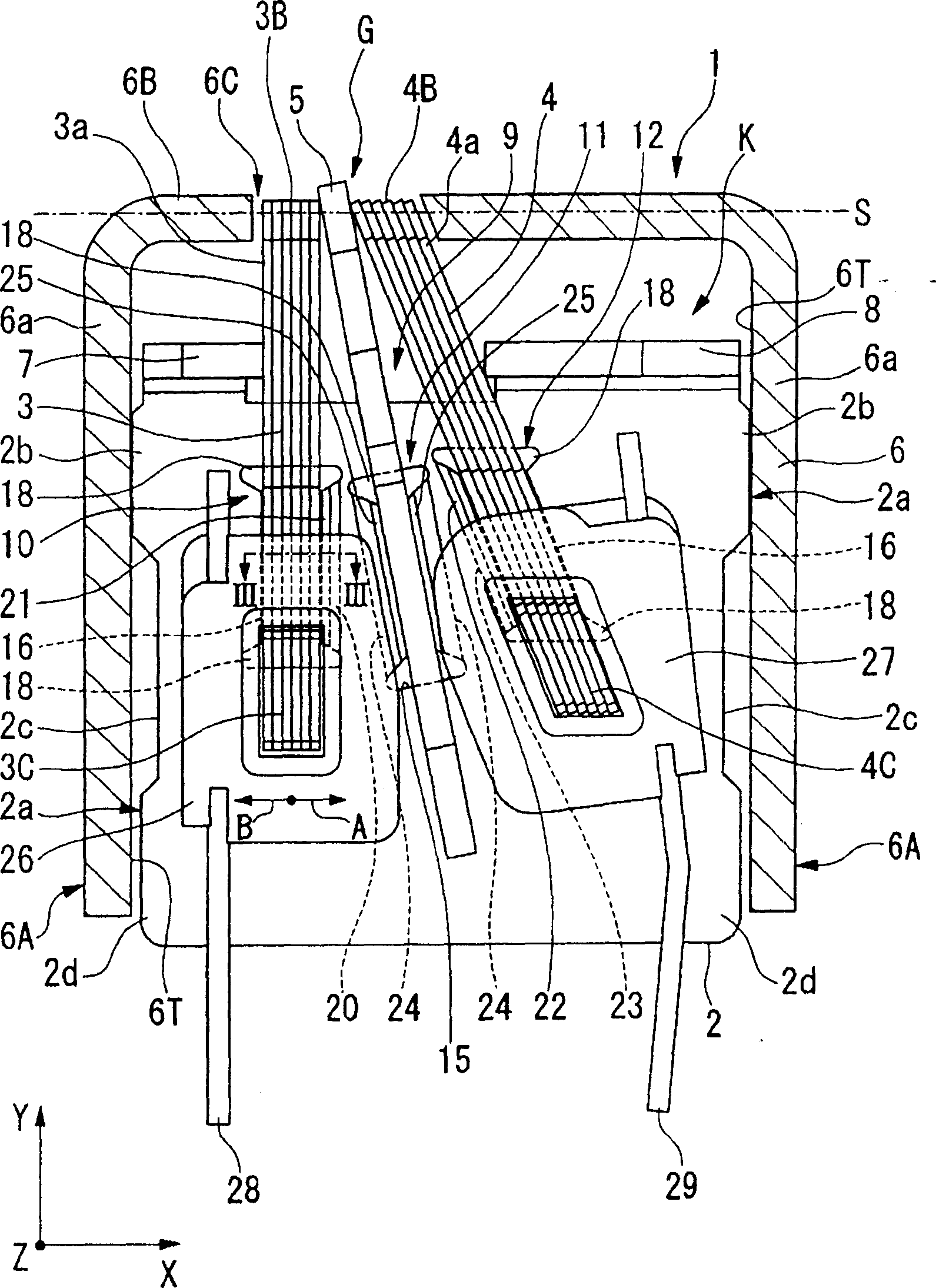
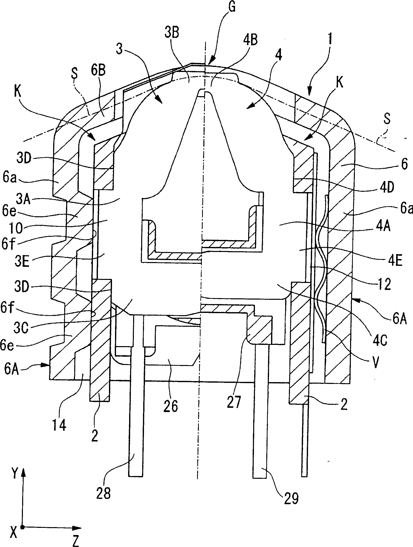
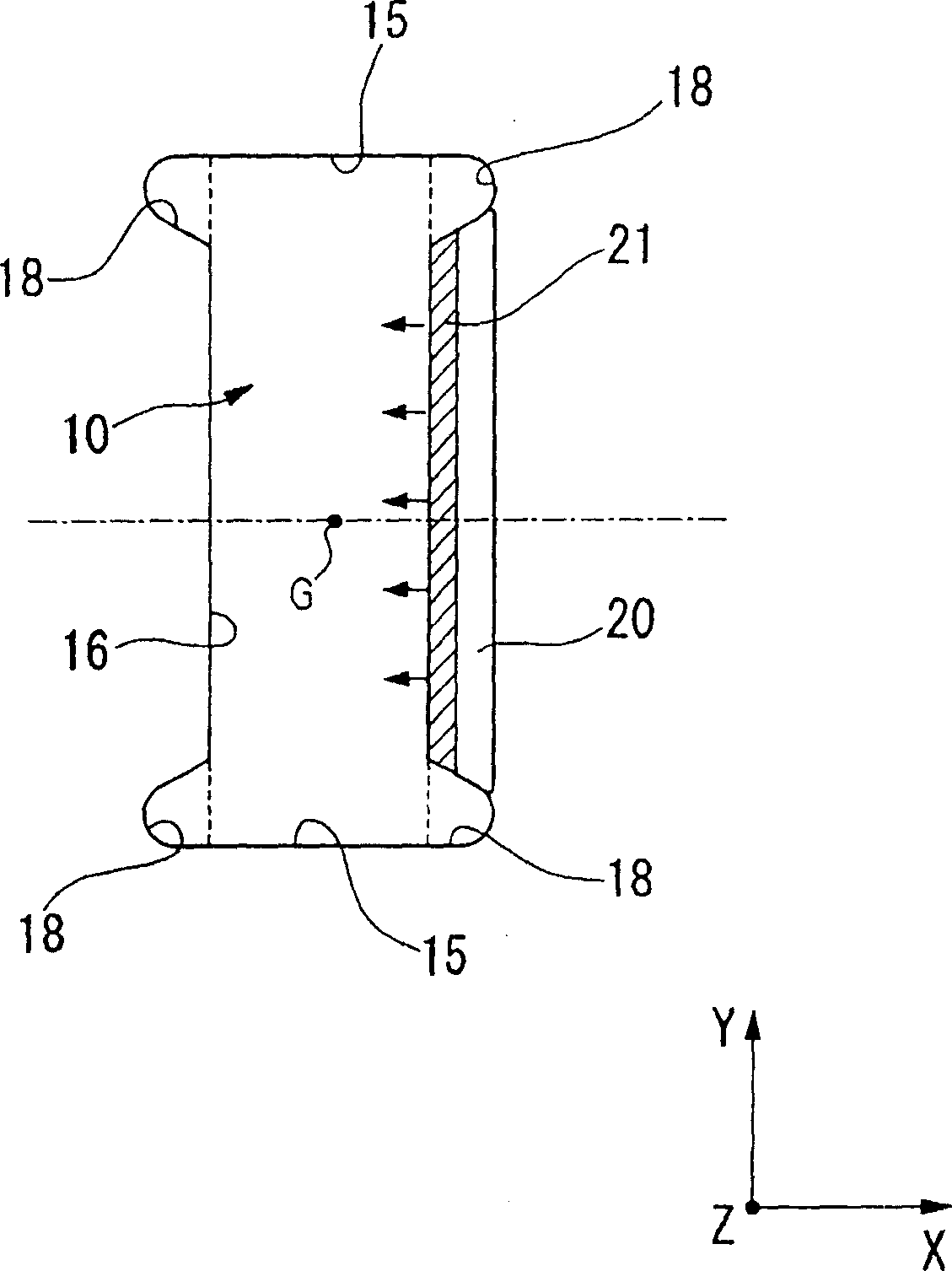
[0052] like figure 1 and figure 2 As shown, on the base member 2 made of plastically processed metal plate, two magnetic core assemblies K with magnetic core halves 3, 4 and shielding plate 5 are assembled, and then both are stored in the shielding case 6, thus constituted The magnetic head 1 of the first embodiment.

[0053] In this embodiment, four peripheral walls 6a form a square cylindrical case 6A, and a front wall 6B is formed to close one side opening of the peripheral wall 6a, and the shield case is constituted by the case 6A and the front wall 6B. 6. The shield cover 6 is integrally formed by deep drawing of a metal material, and a window portion 6C is formed at a partial position of the front wall 6B. In addition, the inside of the shield case 6 is filled with a bonding resin (not shown), and the above-mentioned set of magnet...


PUM


Abstract

Provided is a magnetic head attaching position accuracy of a magnetic core half body for a shield case can be improved. A tilt taper plane 6T is formed so that mutual intervals are made narrower from a rear part of the shield case to a front plane side at a part in which at least tip side both inside parts of a base member 2 is positioned in the both inside parts of the front plane side in the shield case 6, and a press fit part 2b positioned being held by the both taper plane 6T in the tip side of both side parts of the base member 2 is formed.

Description

technical field [0001] The present invention relates to a magnetic head having a magnetic core formed by assembling magnetic core halves inside a shield, a magnetic head device equipped with the magnetic head, a manufacturing method of the magnetic head, and a shield. Background technique [0002] As an example of a dual-channel recording and reproducing type magnetic head for audio frequency, there are known such as Figure 14 As shown, two magnetic core halves 100, 101 formed by stacking a plurality of "C"-shaped magnetic plates are installed on a plate-shaped base member 102, and a pair of base members 102 are accommodated in a shield case 105 to form a magnetic head. 106. [0003] On the above-mentioned base member 102, circular protrusions 108, 109 are protrudingly formed. 112 is fixed to the gap 112 between the engaging pieces 110 and 111 formed by bending the edge side of the base member 102 in a state of sandwiching them. That is, the magnetic core halves 100, 101 ...

Claims


Application Information

Patent Timeline
IPC IPC(8): G11B5/105G11B5/127G11B5/29
Inventor 上村道夫阿部正富
Owner ALPS ALPINE CO LTD
Learn More