Supercharge Your Innovation With Domain-Expert AI Agents!

Capacitive load driving circuit and liquid crystal display

A capacitive load, driving circuit technology, applied in circuit devices, emergency protection circuit devices, emergency protection devices with automatic disconnection, etc., can solve problems such as overheating of output transistors, reduce the number of parts, prevent overheating, and improve safety. Effect

Inactive Publication Date: 2004-09-01
PANASONIC CORP
View PDF1 Cites 7 Cited by
  • Summary
  • Abstract
  • Description
  • Claims
  • Application Information

AI Technical Summary

Problems solved by technology

As a result, there is a problem that the output transistors Q1, Q2 constituting the output circuit 21 are overheated, and an integrated circuit, etc. integrating, for example, a capacitive load driving circuit including the output transistors Q1, Q2 is also overheated.

Method used


Image

  • Capacitive load driving circuit and liquid crystal display
  • Capacitive load driving circuit and liquid crystal display
  • Capacitive load driving circuit and liquid crystal display

Examples


Embodiment Construction

[0059] Hereinafter, embodiments of the present invention will be described with reference to the drawings.

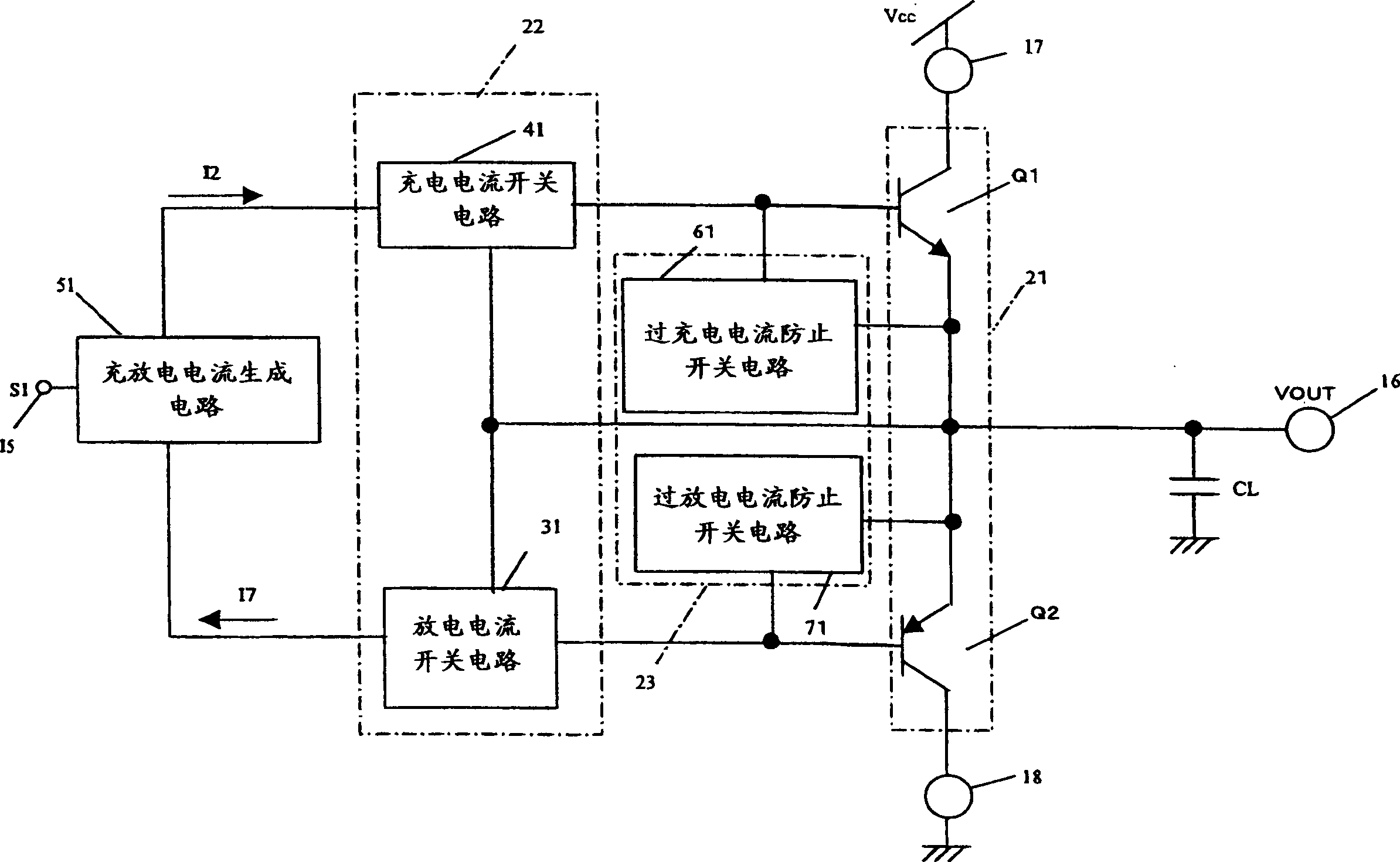
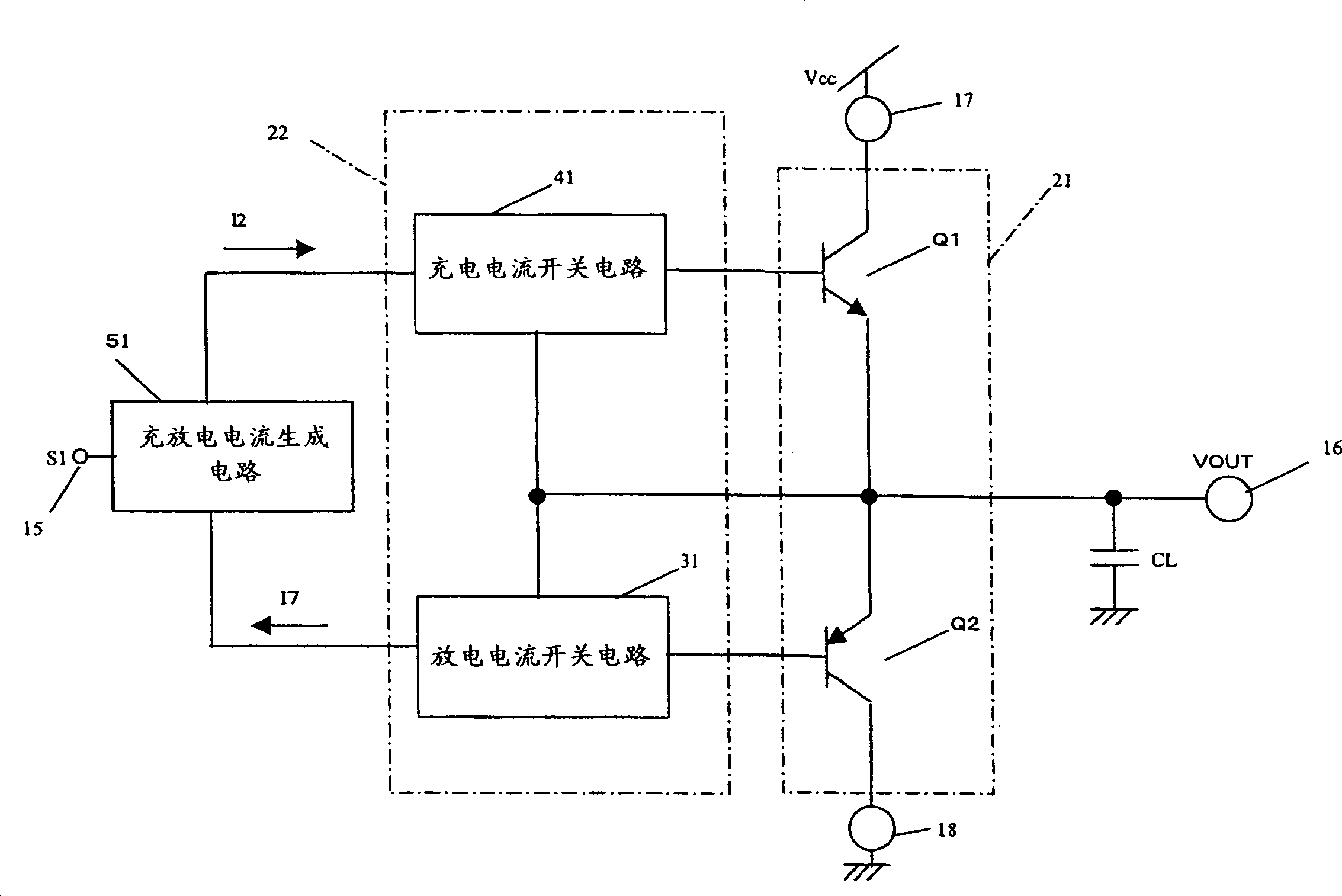
[0060] figure 1 is a circuit diagram showing a schematic configuration of a capacitive load driving circuit according to an embodiment of the present invention. The capacitive load drive circuit is in image 3 The structure shown in is formed by adding an overcurrent protection circuit 23, and other structures are the same as image 3 The capacitive load drive circuit shown in is the same.

[0061] The overcurrent protection circuit 23 detects a short circuit (ground) between the output terminal 16 and the ground terminal 18 to stop or suppress the charging current supply operation of the charging current switch circuit 41 of the charging and discharging control circuit 22 . Furthermore, the overcurrent protection circuit 23 detects a short circuit (connection) between the output terminal 16 and the power supply terminal 17 to stop or suppress the discharge current ex...


PUM


Abstract

An overcurrent is prevented from flowing in an output circuit when a short circuit occurs between an output terminal and a power supply terminal or a ground terminal. For this purpose, provided is an output circuit comprising a power supply terminal, a ground terminal, and an output terminal connected to a capacitive load. Depending on the state of a load control input signal, the output circuit performs selectively a charging-current supplying operation of supplying a charging-current from the power supply terminal to the capacitive load and a discharging-current withdrawing operation of withdrawing a discharging-current from the capacitive load to the ground terminal. Further, an overcharging-current prevention switch is provided for detecting a short circuit between the output terminal and the ground terminal so as to stop or suppress the charging-current supplying operation. Furthermore, an overdischarging-current prevention switch is provided for detecting a short circuit between the output terminal and the power supply terminal so as to stop or suppress the discharging-current withdrawing operation.

Description

technical field [0001] The present invention relates to a capacitive load driving circuit for driving a capacitive load by charging and discharging current, such as a capacitive load driving circuit for driving a common electrode of a liquid crystal panel. In addition, the present invention also relates to a liquid crystal display device using a capacitive load drive circuit. Background technique [0002] Japanese Patent Application Laid-Open No. 2000-174601 and the like describe a capacitive load drive circuit for driving a capacitive load including, for example, a common electrode of a liquid crystal panel. [0003] image 3 is a schematic circuit diagram showing a capacitive load drive circuit proposed by the present inventors previously. like image 3 As shown, in this capacitive load driving circuit, the output circuit 21 has a power supply terminal 17 connected to a power supply line (Vcc line), a ground terminal 18 connected to a ground line, and a capacitor composed...

Claims


Application Information

Patent Timeline
Patent Type & Authority Applications(China)
IPC IPC(8): G09G3/36G02F1/133G09G3/20H02H3/087H03K17/08H03K17/60
CPCH02H3/087G02F1/133
Inventor 天野祐司韮泽敬央滨口英雄
Owner PANASONIC CORP
Features
  • R&D
  • Intellectual Property
  • Life Sciences
  • Materials
  • Tech Scout
  • Unparalleled Data Quality
  • Higher Quality Content
  • 60% Fewer Hallucinations
Learn More