Transmission wireless station, reception wireless station, wireless communication system and wireless communication method

A technology of wireless communication system and wireless station, which is applied in the direction of radio transmission system, communication between multiple stations, transmission system, etc. It can solve problems such as difficult to achieve smooth handover, and achieve the effect of reducing manufacturing cost and reducing volume

Inactive Publication Date: 2004-09-01
NTT DOCOMO INC
View PDF2 Cites 5 Cited by
  • Summary
  • Abstract
  • Description
  • Claims
  • Application Information

AI Technical Summary

Problems solved by technology

at the time of the handover figure 2 In the receiving wireless station 11, it is difficult to realize a smooth handover from the frequency band f1 to the frequency band f2 or from the frequency band f2 to the frequency band f1 because it is necessary to demodulate the received signal after the switcher 14 temporarily switches from the existing frequency band to the desired frequency band.

Method used


Image

  • Transmission wireless station, reception wireless station, wireless communication system and wireless communication method
  • Transmission wireless station, reception wireless station, wireless communication system and wireless communication method
  • Transmission wireless station, reception wireless station, wireless communication system and wireless communication method

Examples


Embodiment 1

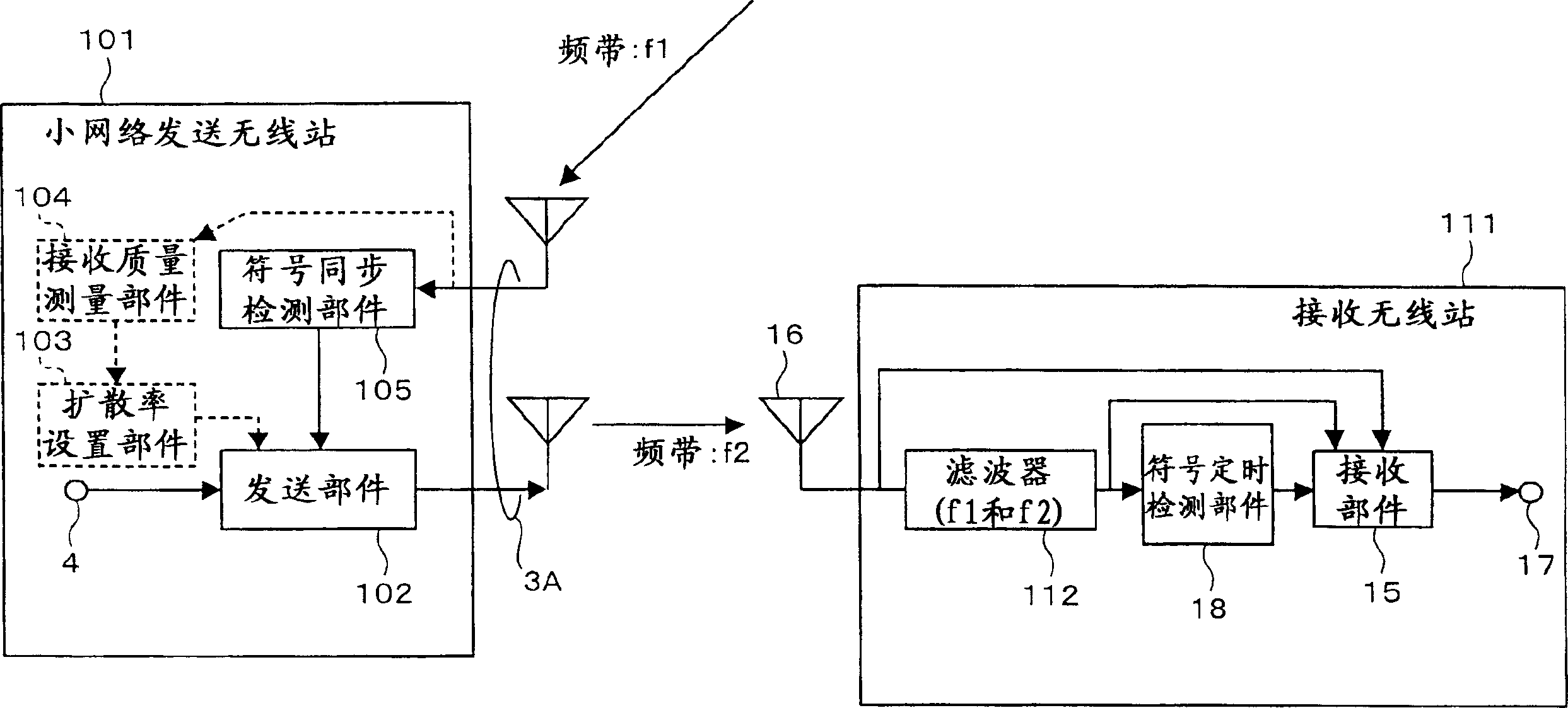
[0054] use image 3 The functional block diagram of the small network sending wireless station 101 and receiving wireless station 111, Figure 4 The diagram showing the timing relationship of the received symbols from the transmitting radio station of the large network and the transmitted symbols of the transmitting radio station of the small network illustrates Embodiment 1 of the present invention. In addition, a case will be described in which a transmission radio station of a large network uses the frequency band f1 and a transmission radio station of a small network uses the frequency band f2. In addition, the "carrier frequency band" in the present invention means a carrier frequency or a subcarrier frequency, and the transmitting wireless station may transmit data using only one carrier.

[0055]In the small network transmitting wireless station 101, the symbol synchronization detection section 105 detects the symbol timing of the data transmitted by the large network ...

Embodiment 2

[0091] Next, use Image 6 The structural diagram of the functional modules of the transmitting wireless station and the receiving wireless station illustrates Embodiment 2. In this embodiment, a transmission wireless station using the frequency band f3 and a transmission wireless station using the frequency band f4 will be described. The transmitting wireless station can be either a large network transmitting wireless station or a small network transmitting wireless station. In addition, the case where two frequency bands are used is described, but the case where three or more frequency bands are used is also the same.

[0092] The transmitting section 202 of the transmitting wireless station 201 and the transmitting section 202 of the transmitting wireless station 221 perform symbol synchronization of transmission symbols by a signal output from the symbol synchronization reference source 230 . That is, the symbols of the data input from the data input terminal 4 of the tra...


PUM


Abstract

The object of the present invention is to achieve smooth hand-over in the radio communication system with a hierarchical cell structure that executes data transmission using orthogonal carrier frequency bands. In the sending radio station to arrange sending symbols in a frequency axis and send signals using one or a plurality of carrier frequency bands, on detecting there having been received one or more carrier frequency band signals pertaining to a transmission system other than that of its own station (SO1), the symbol synchronization will be detected based on the received signal (SO2), and the signal to be sent, will be sent at the symbol sending timing derived based on the detected symbol synchronization (SO3). Therefore, by the correlation between the carrier frequency band signals of the transmission system other than that of its own station and the signal of the station of its own, signals causing no mutual interference can be sent at the symbol sending timing, while the receiving radio station can simultaneously receive signals of a plurality of carrier frequency bands and demodulate the signals. For this reason, smooth hand-over can be achieved.

Description

technical field [0001] The present invention relates to a hierarchical network structure (a so-called network structure in a network), a transmitting wireless station, a receiving A wireless station, the wireless communication system and a wireless communication method. Background technique [0002] In FIG. 1, it is shown that using more than one transmitting wireless station covering an area 90 of a certain range, can receive a signal transmitted from the transmitting wireless station and form an equivalent isotropic transmission power (EIRP) compared with the transmitting wireless station. ) a wireless transmission system of a transmission wireless station of a small and small-scale network 80 . In addition, in this specification, one or more transmitting wireless stations covering a certain area 90 are described as "large-scale network transmitting wireless stations," which will form a small-scale network 80 with a smaller EIRP than that of a large-scale network transmit...

Claims


Application Information

Patent Timeline
Patent Type & Authority Applications(China)
IPC IPC(8): H04B7/26H04L27/26
CPCH04B7/2687H04L27/2662
Inventor 大久保信三大津徹
Owner NTT DOCOMO INC
Why Eureka
Try Eureka