Magnetic sensor and producing method thereof
A magnetic sensor and magnetic field technology, applied in the field of magnetic sensors, can solve problems such as complex manufacturing processes
- Summary
- Abstract
- Description
- Claims
- Application Information
AI Technical Summary
Problems solved by technology
Method used
Image
Examples
no. 1 example
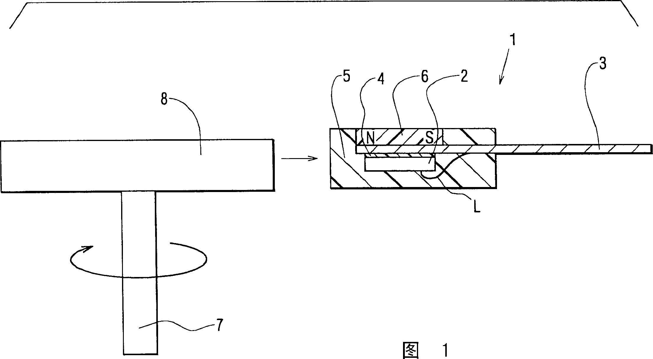
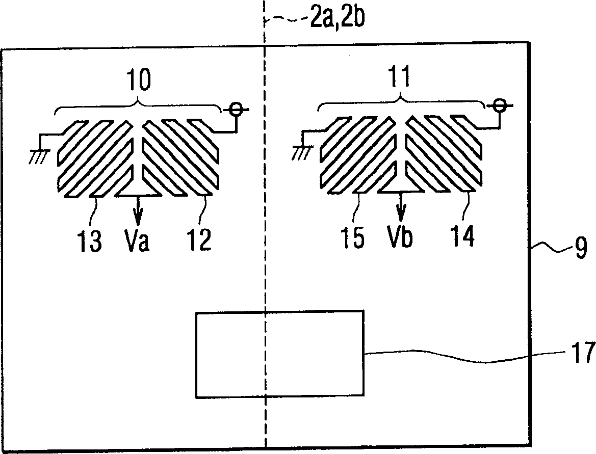
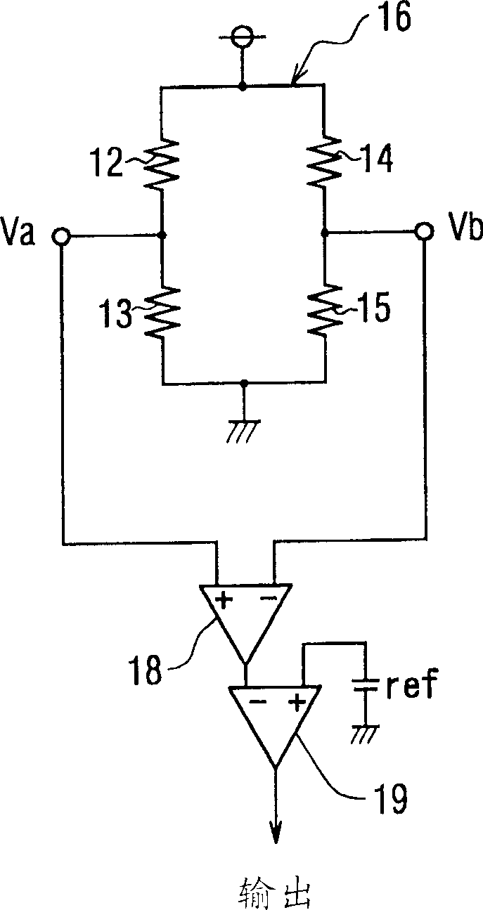
[0034] Now, the present invention will be described in detail with reference to the drawings corresponding to the magnetic sensor according to the first embodiment. 1 is a sectional view of a magnetic sensor and a magnetic rotor (an object to be detected) according to a first embodiment of the present invention. Figure 2A is a plan view of the magnetic sensor chip according to the first embodiment of the present invention, and Figure 2B is a circuit diagram of a circuit configuration of a magnetoresistive pattern according to a first embodiment of the present invention.
[0035] This embodiment provides a magnetic sensor 1 that can be used as a rotation detector for detecting the rotation of a rotating object (including gears) to be detected, such as an engine rotation sensor, a cam angle sensor, a crank angle sensor, an automobile speed sensor, an AT sensor and wheel speed sensor. Referring to FIG. 1 , on the right-hand side of a gear-shaped (its teeth not shown) magnetic ...
no. 2 example
[0054] Now, the present invention is explained with reference to FIG. 6 according to the second embodiment. Common parts of the second embodiment and the first embodiment will not be explained in detail. The present embodiment differs from the first embodiment in that a bias magnet 6 is formed at a portion on one side of the magnetic sensor chip 2 .
[0055] The method according to this embodiment takes advantage of the property that when the Curie temperature is reached, the magnetic material is less magnetized and is thus easily susceptible to external influences. In order to reach the Curie temperature, the lead frame 3 is provided with a heat generating portion, which is a part of the lead frame 3 reduced in shape to have increased resistance, and generates heat with a large current flowing therethrough. The heat generating portion is formed in the vicinity of an optimum position where it is desired to form the above-mentioned bias magnet 6 within the lead frame 3 .
[0...
no. 3 example
[0059] Now, referring to the Figure 7 to explain the present invention. Common parts of the third embodiment and the above-mentioned embodiments will not be explained in detail. This embodiment differs from the above-described embodiments in that the bias magnet 6 is formed inside the lead frame 3 .
[0060] The method according to this embodiment includes the following steps: using a magnetized yoke to magnetize the required optimal position so as to form the above-mentioned bias magnet 6 in the lead frame 3 made of known copper or 42Ni-Fe, etc., thereby forming Bias 6. In this way, the trace frame 3 is used as a bias magnet 6 . Therefore, a conventionally available lead frame 3 can be used to form the bias magnet 6 without mixing magnetic powder into the molding material 5, thereby facilitating manufacturing.
PUM
 Abstract
Description
Claims
Application Information
 - R&D
- Intellectual Property
- Life Sciences
- Materials
- Tech Scout
- Unparalleled Data Quality
- Higher Quality Content
- 60% Fewer Hallucinations
Browse by: Latest US Patents, China's latest patents, Technical Efficacy Thesaurus, Application Domain, Technology Topic, Popular Technical Reports.
© 2025 PatSnap. All rights reserved.Legal|Privacy policy|Modern Slavery Act Transparency Statement|Sitemap|About US| Contact US: help@patsnap.com


