Flat display panel and method of dividing the flat display panel

A flat display and liquid crystal display panel technology, applied in stone processing equipment, instruments, glass manufacturing equipment, etc., can solve the problems of longer processing flow and lower product value, and achieve the effect of simplifying the operation process

Inactive Publication Date: 2004-09-08
MITSUBOSHI DIAMOND IND CO LTD
View PDF1 Cites 11 Cited by
  • Summary
  • Abstract
  • Description
  • Claims
  • Application Information

AI Technical Summary

Problems solved by technology

Therefore, the processing flow of the device becomes longer and the system structure becomes larger
In addition, in the step (4) of cutting the glass substrate 14, if the cutting force is too large, defects will be generated on the cut surfaces of the glass substrate 12 and the glass substrate 14 and the value of the product will be reduced.

Method used


Image

  • Flat display panel and method of dividing the flat display panel
  • Flat display panel and method of dividing the flat display panel
  • Flat display panel and method of dividing the flat display panel

Examples


Embodiment Construction

[0027] Embodiments of the present invention will be described below with reference to the drawings.

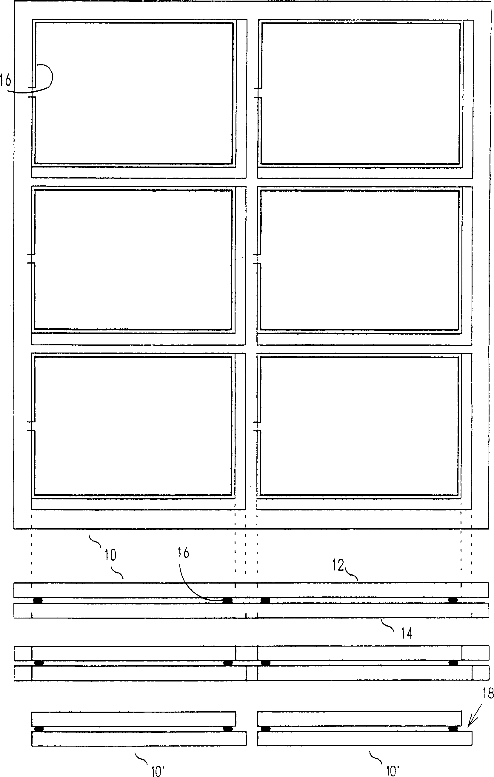
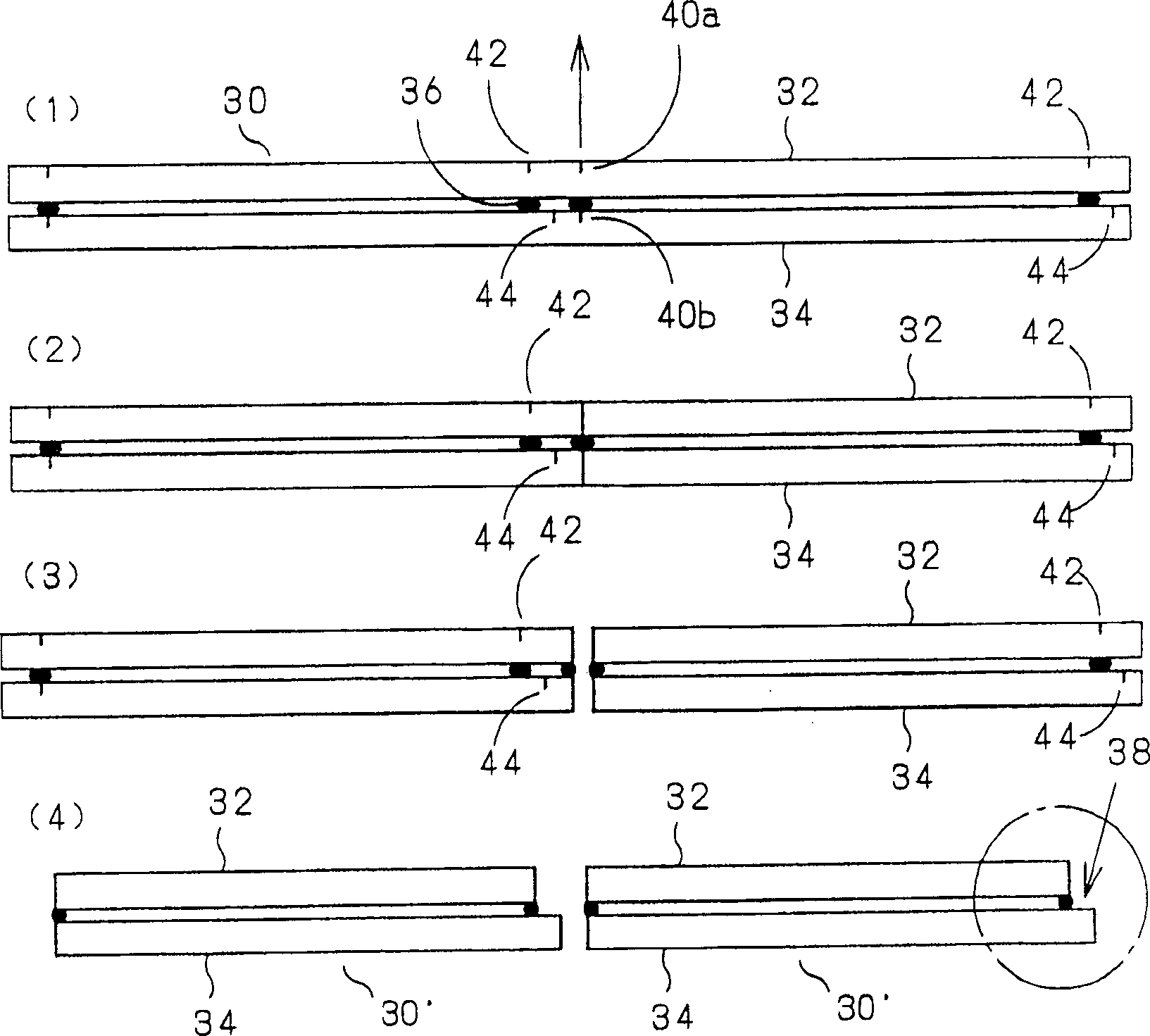
[0028] image 3 It is a figure for demonstrating the manufacturing method of the liquid crystal display panel which is one kind of flat display panel of this invention. A large-sized liquid crystal display panel 30 is manufactured by making two glass substrates 32 and 34 face each other and bonding them together with a sealant 36 . On the inner surfaces of the glass substrates 32 and 34 , various electronic control circuits (TFT arrays, etc.) required for display functions are formed. In addition, between the two glass substrates 32 and 34, a part of the sealing material 36 is opened to form a gap for introducing a functional material (liquid crystal). In addition, the terminal portion 38 is a portion serving as a terminal of a TFT array formed on one glass substrate 34 . The composition and figure 1 The prior art examples shown are identical. Scribe lines 40a are formed ...


PUM


Abstract

A flat display panel, comprising two sheets of fragile material substrates stuck to each other, wherein at least one of the two sheets of fragile material substrates has a scribed face and the scribed face of the at least one of the fragile material substrates is opposed to the non-scribed face of the other fragile material substrate, both two sheets of the fragile material substrates may have scribed faces or only one sheet of the fragile material substrate may have a scribed face, in the latter, the other fragile material substrate can be scribed after sticking, and, at the time of dividing, when the scribed face is positioned on the upper surface side, for example, a flat panel is deflected in reverse V-shape to simultaneously divide both fragile material substrates.

Description

technical field [0001] The invention relates to a flat display panel in which brittle material substrates such as a liquid crystal panel are bonded together and a cutting method thereof. Background technique [0002] As products related to flat display panels, flat display panels such as liquid crystal display panels, liquid crystal projector substrates, and organic EL elements are used in various fields as information transmission mechanisms between machines and people. In the bonding substrate used in such a flat display panel, various electronic control circuits and the like required for a display function are formed on the inner surface thereof, and two sheets are bonded facing each other. The functional material sealed in the gap provided between the two substrates is controlled by the above-mentioned electronic control circuit, thereby functioning as a display device in the form of images visible to the eyes. [0003] Hereinafter, the prior art of a liquid crystal pan...

Claims


Application Information

Patent Timeline
Patent Type & Authority Applications(China)
IPC IPC(8): B28D5/00C03B33/033C03B33/07G02F1/1333
CPCB28D5/0023B28D5/0011C03B33/076B28D5/0052G02F1/133351C03B33/033B28D5/0029Y02P40/57G02F1/13
Inventor 若山治雄
Owner MITSUBOSHI DIAMOND IND CO LTD
Why Eureka
Try Eureka