Supercharge Your Innovation With Domain-Expert AI Agents!

DC/DC converter synchronous rectification circuit

A synchronous rectification and converter technology, applied in the direction of converting DC power input to DC power output, instruments, electrical components, etc., can solve the problem that the output voltage MOS transistor Sa of the isolated differential circuit is turned on, and the DC-DC converter cannot be applied in direct parallel connection. It can avoid the reverse conduction, reduce the Vds voltage stress pulse width and the structure is simple.

Inactive Publication Date: 2004-09-15
EMERSON NETWORK POWER CO LTD
View PDF0 Cites 24 Cited by
  • Summary
  • Abstract
  • Description
  • Claims
  • Application Information

AI Technical Summary

Problems solved by technology

For the same reason, the DC-DC converter using this synchronous rectification drive circuit cannot be applied in the occasion where the output can be directly connected in parallel.
[0006] Even if the capacitor C1 is used to resonate with the excitation inductance Lm of the driving transformer T2 and the charge of the capacitor C2 is maintained when the power is turned off, when the power is turned off when the duty cycle is small, the voltage on the capacitors C1 and C2 is proportional to the duty cycle, and PWM output impedance and the attenuation effect of R2, the output voltage of the isolation differential circuit is too low to turn on the MOS transistor Sa to discharge the gate charge of SR2, and SR2 will still conduct in reverse
[0007] In this circuit, when the DC-DC converter is turned off, because the freewheeling tube SR2 is not turned off in time, the freewheeling tube will conduct in reverse, the output voltage will have negative pressure, and the converters cannot be operated in parallel.

Method used


Image

  • DC/DC converter synchronous rectification circuit
  • DC/DC converter synchronous rectification circuit
  • DC/DC converter synchronous rectification circuit

Examples


Embodiment Construction

[0028] The content of the present invention will be further elaborated below in conjunction with the accompanying drawings and embodiments.

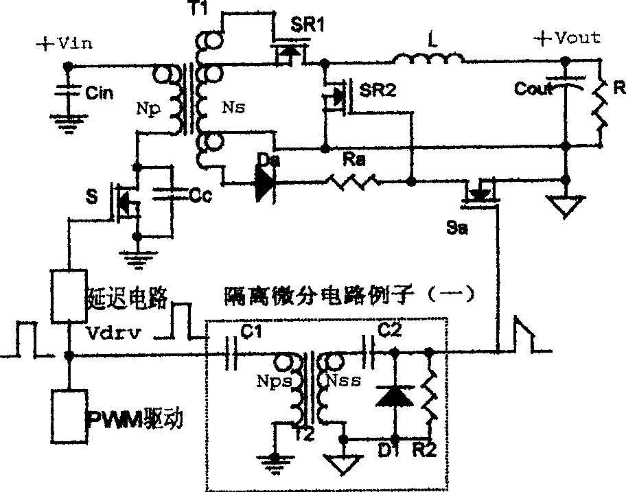
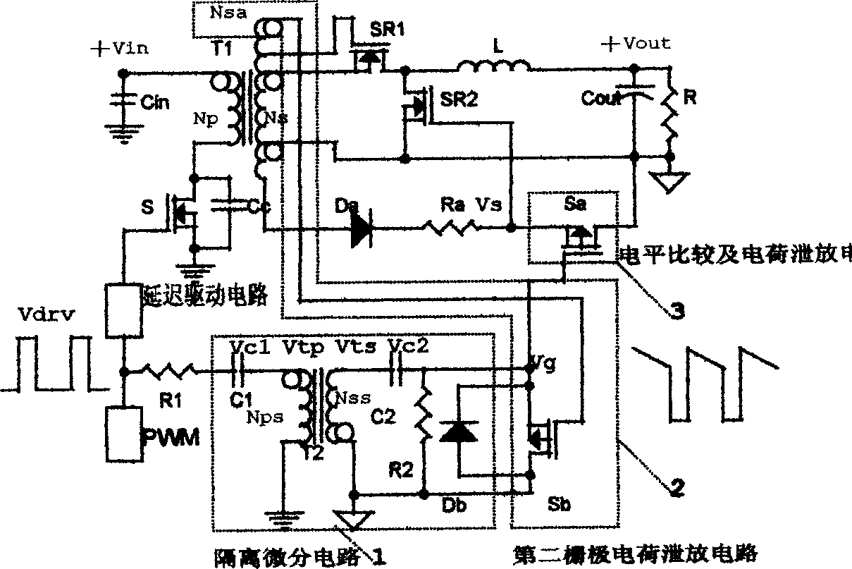
[0029] Such as Figure 3a As shown, the DC / DC converter synchronous rectification circuit includes

[0030] delay drive circuit;

[0031] The main power tube S is connected to the delay driving circuit;

[0032] Transformer T1 is connected to the drain of the main power tube;

[0033] The secondary winding Ns of the transformer T1, the first rectifier SR1, the inductor L connected to the drain of the first rectifier SR1, and the output capacitor Cout are sequentially connected to form a closed loop;

[0034] The drain of the second rectifier SR2 is connected to the drain of the first rectifier SR1, and the source is connected to the connection point of the output capacitor Cout and the secondary winding Ns;

[0035] The driving circuit of the second rectifier SR2 includes a diode Da connected to the secondary winding Ns, a resistor R...


PUM


Abstract

The rectification circuit comprises delayed drive circuit, main circuit, first rectifying tube SRl, second rectifying tube SR2, drive circuit of second rectifying tube SR2, level comparison and grid charge bleeder circuit, isolation drive circuit, second grid charge bleeder circuit. The invention solves issues of not turning off synchronous rectification MOS transistor in due course or overlong turning off time existed in its drive circuit utilized in general DC / DC convertor with low voltage and large current in present technique. The invented circuit reduces stress pulse width of drain-source electrodes Vds voltage in main power MOS transistor, as well as prevents reversed ducting of synchronous rectification tube, and ducting of SRl, SR2 at same time. The invention possesses features of simple structure, low cost and high efficiency.

Description

[technical field] [0001] The invention relates to a synchronous rectification technology of a DC / DC converter in the field of power electronics. [Background technique] [0002] With the development of information technology, digital chips require the power supply voltage of the module power supply to be lower and lower, the power supply current to be larger and the power supply power to be higher and higher. A single module can no longer meet the power supply requirements, and instead, multiple module power supplies run in parallel. Meanwhile, synchronous rectification technology for DC-DC converter is widely adopted in DC-DC converter rectification technology due to its higher efficiency than Schottky rectification technology. However, since the conduction characteristics of the synchronous rectification MOS transistor are different from the unidirectional conduction characteristics of the Schottky diode, the synchronous rectification MOS transistor can conduct bidirection...

Claims


Application Information

Patent Timeline
Patent Type & Authority Applications(China)
IPC IPC(8): H02M3/335
CPCY02B70/1475Y02B70/10
Inventor 雷兴华
Owner EMERSON NETWORK POWER CO LTD
Features
  • R&D
  • Intellectual Property
  • Life Sciences
  • Materials
  • Tech Scout
  • Unparalleled Data Quality
  • Higher Quality Content
  • 60% Fewer Hallucinations
Learn More