
Nuclear magnetic resonance imager and nuclear magnetic resonance imaging method

A technology of nuclear magnetic resonance imaging and equipment, which is applied in the direction of using nuclear magnetic resonance imaging system for measurement, magnetic resonance measurement, chemical instruments and methods, etc., can solve the problems of reducing image quality, and achieve the goal of not reducing image quality and eliminating fold artifacts Effect

Inactive Publication Date: 2010-05-05
GE MEDICAL SYST GLOBAL TECH CO LLC
View PDF2 Cites 2 Cited by
  • Summary
  • Abstract
  • Description
  • Claims
  • Application Information

AI Technical Summary

Problems solved by technology

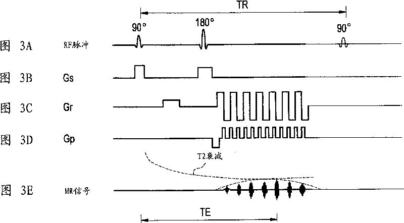
[0005] However, the above-mentioned nuclear magnetic resonance imaging apparatus has a problem that when the nuclear magnetic resonance signal is received, for example, in an EPI pulse sequence and an image is generated using the above-mentioned parallel imaging technique, the image quality is degraded due to a non-uniform magnetic field, etc.

Method used


Image

  • Nuclear magnetic resonance imager and nuclear magnetic resonance imaging method
  • Nuclear magnetic resonance imager and nuclear magnetic resonance imaging method
  • Nuclear magnetic resonance imager and nuclear magnetic resonance imaging method

Examples


Embodiment Construction

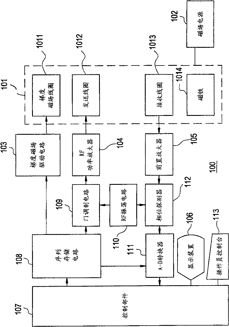
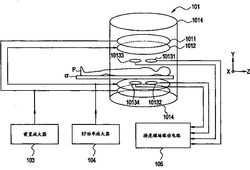
[0028] The magnetic resonance imaging apparatus 100 according to the first embodiment of the present invention implements a parallel imaging technique, which is used, for example, to generate images containing convolution artifacts from signals received by multiple coils, to generate images according to different sensitivity distributions in the multiple coils The image with the wrinkling artifact eliminated, and a technique in which the magnetic resonance imaging apparatus 100 phases the signals received by the multiple coils according to the correction signal received by one of the multiple coils and combined with additional information in the phase encoding direction Correction processing, and according to the signals received by multiple coils, which have undergone phase correction processing, and the different sensitivity distributions in the multiple coils, the wrinkle artifacts in the image are eliminated.

[0029] Convolution artifacts are caused by aliasing when multip...


PUM


Abstract

For the purpose of removing wraparound artifacts without degrading image quality of an image, there are provided a phase correcting section (1072) for conducting phase correction processing on received signals in an actual scan based on a reference signal as a corrective signal received by one of a plurality of receive coils (1013), without applying a gradient magnetic field Gp in a phase encodingdirection, and an unfolding section (1075) for removing wraparound artifacts in an image based on the signals received by the plurality of receive coils (1013) in the actual scan and subjected to thephase correction processing by the phase correcting section (1072), and on the difference in sensitivity distribution among the plurality of receive coils (1013), so that the phase correction processing is conducted while preserving the relative phase relationship among the coils, and unfolding processing (removal processing) is conducted using the result of such phase correction processing.

Description

technical field [0001] The present invention relates to a nuclear magnetic resonance imaging apparatus and a nuclear magnetic resonance imaging method for generating images based on nuclear magnetic resonance signals generated, for example, from hydrogen atoms in a subject. Background technique [0002] Magnetic resonance imaging (MRI) devices are known for producing images which represent, for example, the density distribution or the relaxation time distribution of atomic nuclei from the MRI signal. [0003] Parallel imaging technology has been widely known in recent years, which utilizes multiple receiving coils for high-speed scanning, while the field of view (FOV) is reduced in the phase encoding direction, from the inclusion of warping artifacts according to the different sensitivity distribution among multiple coils. Eliminates wrinkling artifacts from aliasing in your images and obtains images with a large field of view (sometimes referred to as full FOV). (See eg Pr...

Claims


Application Information

Patent Timeline
Patent Type & Authority Patents(China)
IPC IPC(8): A61B5/055G01R33/20G02B6/12G01R33/34G01R33/48G01R33/54G01R33/561G01R33/565G02F1/313G02F1/35H01L27/15H01S5/00
CPCG01R33/5611G01R33/56545F24F6/12C02F1/4672F24F6/10F24F2006/008
Inventor 池崎吉和
Owner GE MEDICAL SYST GLOBAL TECH CO LLC
Learn More