Thin-wall drum member for cast-in-situs reinforced concrete

A technology of reinforced concrete and thin-walled cylinders is applied in the directions of building components, building structures, floor slabs, etc., which can solve the problems of relative fixation and positioning trouble, affecting the construction progress, etc.

Inactive Publication Date: 2004-09-22
湖南邱则有专利战略策划有限公司
View PDF1 Cites 4 Cited by
  • Summary
  • Abstract
  • Description
  • Claims
  • Application Information

AI Technical Summary

Problems solved by technology

However, with the advancement of construction technology, in the past, the laying of individual pipes one by one has affected the construction progress, and the relative fixing and positioning of each other has become too troublesome

Method used


Image

  • Thin-wall drum member for cast-in-situs reinforced concrete
  • Thin-wall drum member for cast-in-situs reinforced concrete
  • Thin-wall drum member for cast-in-situs reinforced concrete

Examples


Embodiment Construction

[0033] The present invention will be further described below in conjunction with drawings and embodiments.

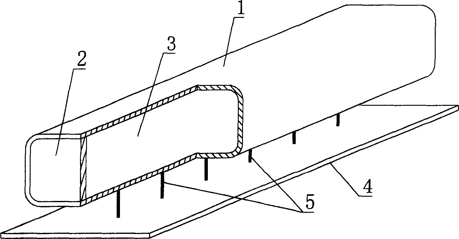
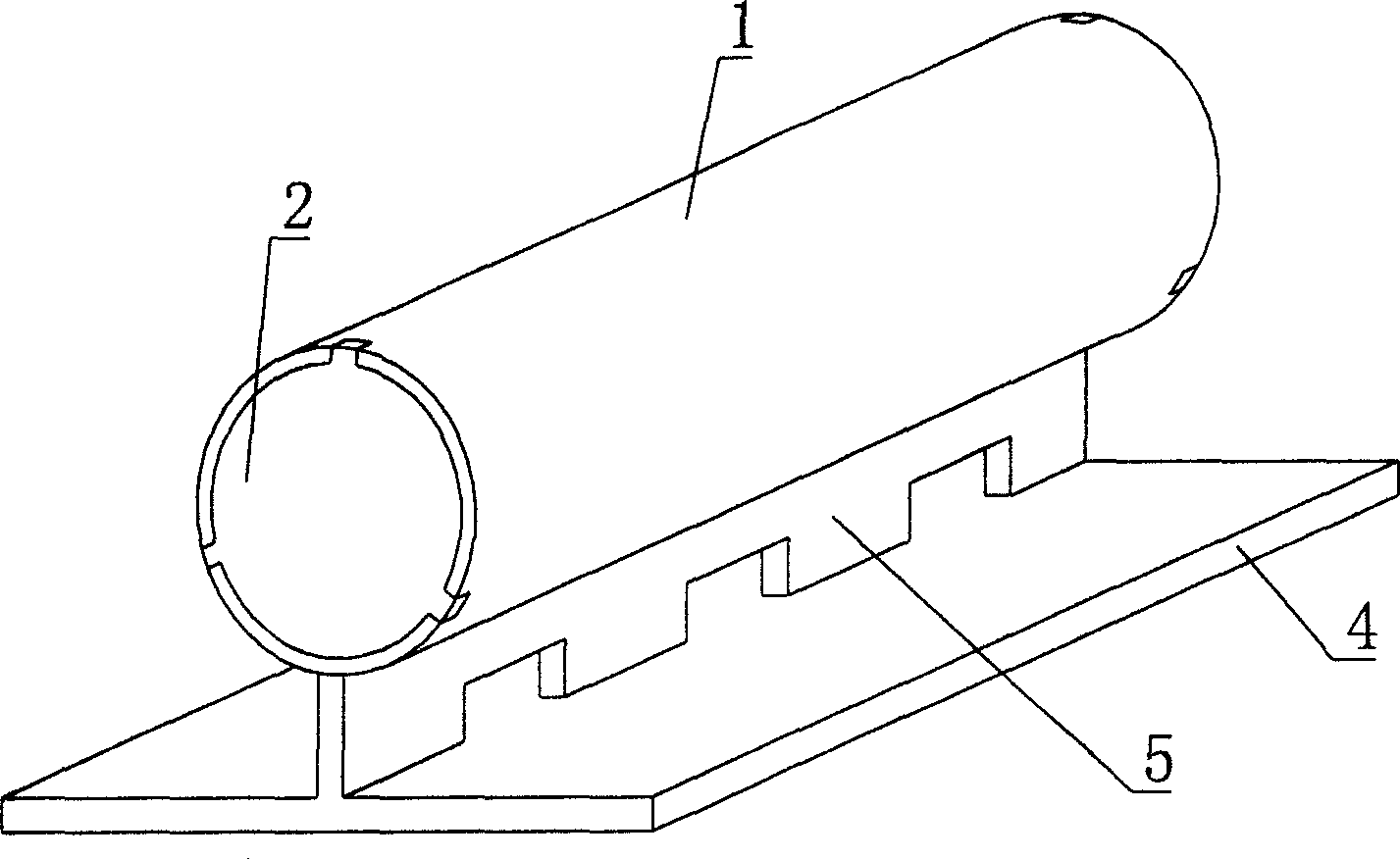
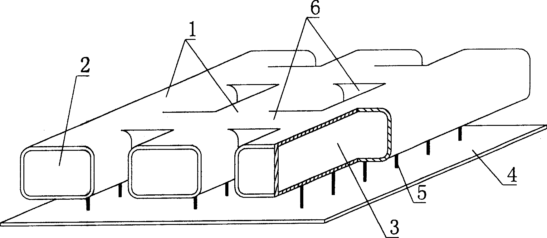
[0034] As shown in the drawings, the present invention includes a hard thin-walled pipe 1 and a plug 2. The plug 2 seals both ends of the hard thin-walled pipe 1 to form a closed cavity 3, and is characterized in that it also includes a bottom plate 4, a connecting Part 5, at least one hard thin-walled pipe 1 is connected to the bottom plate 4 through the connecting part 5 to form a whole. figure 1 It is a schematic diagram of the structure of Embodiment 1 of the present invention. In each accompanying drawing, 1 is a hard thin-walled pipe, 2 is a plug, 3 is a closed cavity in a thin-walled pipe, 4 is a bottom plate, and 5 is a connector. Each accompanying drawing Among them, those with the same number have the same description. like figure 1 As shown, a rigid thin-walled pipe 1 is connected to the bottom plate 4 as a whole through a connecting piece 5 .

[0035] The...


PUM


Abstract

A thin-wall pipe member used as filler in in-situ pouring concrete is composed of thin-wall hard pipe and two blocking ends for enclosing both ends of said thin-wall hard pipe to form a closed cavity. It has also a bottom plate and several linking parts for linking said pipe to the bottom plate. When the floor is constructed, said thin-wall pipe member can be directly put on supporting frame for pouring concrete. Its advantages are high strength, light weight, and high resistance to deformation and earthquake.

Description

(1) Technical field [0001] The invention relates to a thin-walled tube component for filling cast-in-place reinforced concrete. (2) Background technology [0002] At present, in the prior art, the hole-forming components of the cast-in-place hollow floor slab are permanent mandrels, such as paper tubes, plastic tubes, metal bellows, and lightweight materials for mandrels. These tubular mandrels or components are mainly considered to evacuate the concrete and reduce the weight of the floor slab. For example, the patent No. ZL99249775.8 applied by the applicant is a utility model patent named "fiber-reinforced thin-walled tube for filling cast-in-place reinforced concrete". It consists of a hard thin-walled tube and plugs at both ends. The head seals both ends of the hard thin-walled tube to form a closed cavity. The hard thin-walled tube wall is composed of a matrix and a cementitious material. The matrix can be glass fiber or carbon fiber or organic fiber or non-woven fabri...

Claims


Application Information

Patent Timeline
Patent Type & Authority Applications(China)
IPC IPC(8): E04B5/36
Inventor 邱则有
Owner 湖南邱则有专利战略策划有限公司
Why Eureka
Try Eureka