
Optical collimator structure

A collimator and optical technology, applied in the direction of optics, optical components, instruments, etc., can solve problems such as difficult to reduce manufacturing costs, high cost processing and manufacturing

Inactive Publication Date: 2004-09-22
SHINKO ELECTRIC IND CO LTD
View PDF2 Cites 3 Cited by
  • Summary
  • Abstract
  • Description
  • Claims
  • Application Information

AI Technical Summary

Problems solved by technology

In addition, in order to manufacture the conventional optical collimator structure, processing is required, such as YAG welding the sleeve 24 to the sleeve 16, while causing some problems, such as very expensive processing and manufacturing
In addition, the conventional optical structure has a large number of parts, such as: the optical lens 20 and the sleeve 24, which makes it difficult to reduce the manufacturing cost

Method used


Image

  • Optical collimator structure
  • Optical collimator structure
  • Optical collimator structure

Examples


Embodiment Construction

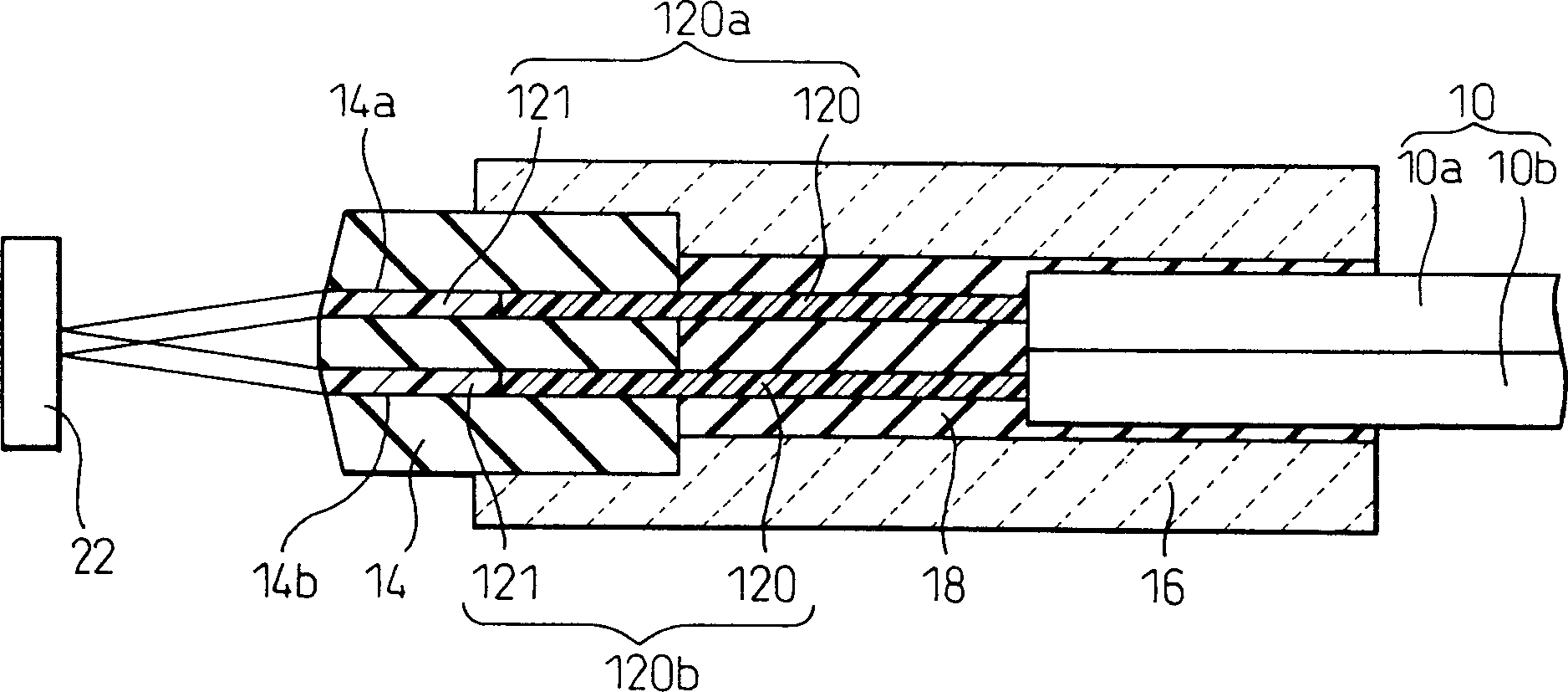
[0023] figure 1 Shown is the optical collimator structure of one embodiment of the present invention, described optical collimator structure is made with optical fiber assembly 10, and optical fiber assembly 10 comprises first unitary optical fiber (unitary optical fiber) 10a and a second unitary optical fiber 10b, They each have a core 120 . The optical collimator structure of the present invention is characterized in that the optical collimator structure is manufactured using an optical fiber assembly 10 having a graded-index optical fiber (GI optical fiber) 14a (or 14b), the GI optical fiber 14a ( or 14b) is welded to the end of the core 120 of each single mode fiber (SMFs) 10a, 10b forming the fiber optic assembly 10, so that each single mode fiber has an optical collimator structure.

[0024] figure 2 An example of a single-core fiber collimator structure is shown in which a GI fiber 121 is welded to the end of the core 120 of the single-mode fiber 100 . In order to ...


PUM


Abstract

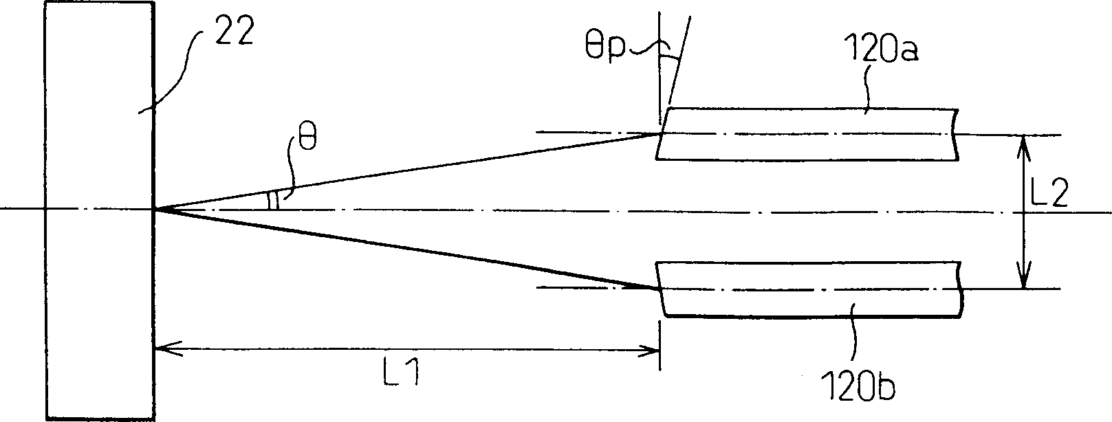
An optical collimator structure comprising an optical fiber assembly of a plurality of unitary single-mode optical fibers each having a core, and a ferrule for supporting the optical fiber assembly inserted partially therein and bonded thereto, wherein the core has a graded index optical fiber bonded to the end face thereof, the graded index optical fiber along with the end portion of the core to which the graded index optical fiber is bonded being inserted in a hole of a capillary provided at an end of the ferrule, and the end face of the graded index optical fiber for emitting or receiving a beam of light has a tilt angle relative to the optical axis of the optical collimator structure.

Description

technical field [0001] The present invention relates to optical collimator structures, and more particularly to optical collimator structures utilizing optical fibers having multiple cores. Background technique [0002] In the field of optical communication, various optical path modules are used, for example, to combine and branch signal light, and to switch optical paths. The optical collimator structure has such a configuration that it emits or receives parallel light flux from an optical fiber. Optical collimator structures include those having a collimator structure using an optical fiber with two cores, in addition to those that use a single-core fiber to make signal light into a parallel light flux, such as Figure 5 shown (see, eg, Japanese Unexamined Patent Publication JP 9-230169 and Japanese Unexamined Patent Publication JP 2002-267876A). [0003] exist Figure 5 In , reference numeral 10a denotes a first optical fiber for inlet, and reference numeral 10b denotes ...

Claims


Application Information

Patent Timeline
Patent Type & Authority Applications(China)
IPC IPC(8): G02B6/26G02B6/32G02B27/30
CPCG02B27/30G02B6/32
Inventor 立岩昭彦
Owner SHINKO ELECTRIC IND CO LTD
Learn More