Deflection coil for deflector

A deflection device and deflection coil technology, applied in the direction of electrode devices and related components, cathode ray tubes/electron beam tubes, discharge tubes, etc., can solve problems such as inconvenient labor and increased material costs

Inactive Publication Date: 2004-09-29
SAMSUNG ELECTRO MECHANICS CO LTD
View PDF0 Cites 0 Cited by
  • Summary
  • Abstract
  • Description
  • Claims
  • Application Information

AI Technical Summary

Problems solved by technology

[0025] However, a problem with the method of fixing the auxiliary coil 24 using the strap 25 is that the process of attaching or detaching the strap 25 must be pe...

Method used


Image

  • Deflection coil for deflector
  • Deflection coil for deflector
  • Deflection coil for deflector

Examples


Embodiment Construction

[0041] Reference is now made to the drawings, wherein like numerals are used for like or like parts throughout the different drawings.

[0042] Hereinafter, a deflection yoke for a deflection device according to the present invention will be described in detail with reference to the accompanying drawings.

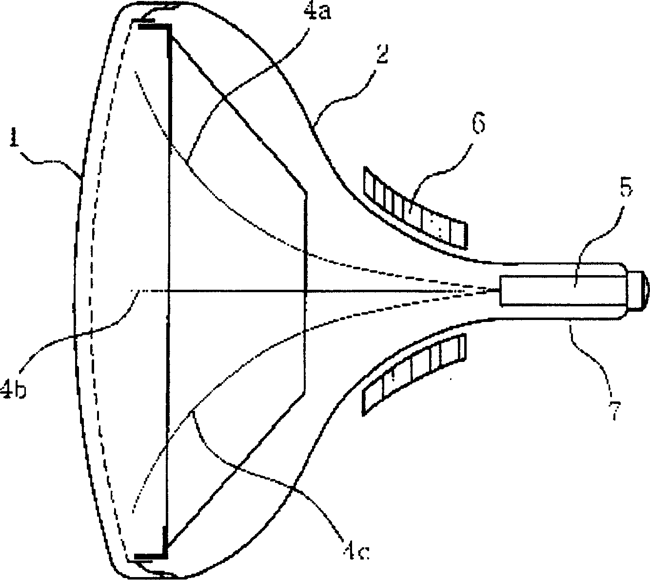
[0043] Such as Figure 5 The deflection yoke shown comprises a neck portion 31 in contact with the neck side end of the isolator, a screen portion 32 in contact with the screen side end of the isolator, a main coil 33 connecting the screen portion 32 to the neck portion 31, An auxiliary coil 34 is connected to the main coil 33 to adjust the characteristics of the main coil 33, and a bridge 35 is connected to the auxiliary coil 34 to the main coil 33 so as to prevent the auxiliary coil 34 from moving.

[0044] The auxiliary coil 34 is located at the center of the main coil 33, and is formed to be connected to the neck portion 31 at its lower end so as to form a closed shape ...


PUM


Abstract

The present invention relates generally to a deflection yoke for a color television, and more particularly to a deflection yoke, in which an auxiliary coil provided to a deflection coil that is a part of a deflection yoke is stably supported, thereby reducing the non-uniformity of assembly and controlling picture characteristics, thus greatly improving the quality of a cathode ray tube. The deflection coil includes a main coil comprising a screen portion, a neck portion and a body portion for connecting the screen portion to the neck portion, an auxiliary coil positioned at a center of the main coil, and connected to the neck portion at its lower ends to form a closed shape, and bridges for connecting an upper end of the auxiliary coil to the main coil to prevent movement of the auxiliary coil.

Description

technical field [0001] The present invention relates generally to deflection yokes for use in color television sets, and more particularly to deflection yokes in which auxiliary coils of deflection yokes which are part of the deflection yoke are rigidly supported, thereby reducing assembly inconsistencies and The characteristics of the image are controlled, thereby significantly improving the quality of the cathode ray tube. Background technique [0002] Generally, the deflection criterion of an electron beam emitted from an electron gun is applied to a cathode ray tube (hereinafter referred to as a CRT). Horizontal and vertical deflection magnetic fields should be applied to the neck of the CRT in order to emit electron beams. [0003] The coils used to form the deflection magnetic field are horizontal and vertical deflection coils, which are placed perpendicular to each other. Horizontal and vertical deflection coils and cores form the deflection unit. [0004] A genera...

Claims


Application Information

Patent Timeline
IPC IPC(8): H01J29/56H01J29/70H01J29/76
CPCH01J2229/5687H01J2229/7033H01J29/762H01J29/566H01J29/703H01J29/76
Inventor 洪允基赵源一
Owner SAMSUNG ELECTRO MECHANICS CO LTD
Why Eureka
Try Eureka