Development roller
A technology for developing rollers and intermediate layers, applied in the field of developing rollers, which can solve problems such as increased residual charge
- Summary
- Abstract
- Description
- Claims
- Application Information
AI Technical Summary
Problems solved by technology
Method used
Image

Examples
Embodiment 1
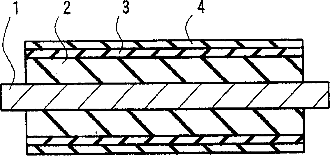
[0028] In order to manufacture the developing roller, the shaft body 1, the forming material (mixture) of the innermost layer 2, the forming material (coating liquid) of the intermediate layer 3, the forming material (coating liquid) of the outermost layer 4, and the A cylindrical mold for the innermost layer 2, etc. As the above-mentioned shaft body 1 , a solid cylindrical shaft body made of iron with a diameter of 8 mm was prepared.
[0029] [Preparation of the forming material (mixture) of the innermost layer 2]
[0030] Conductive silicone rubber (KE1357 A / B, manufactured by Shin-Etsu Chemical Co., Ltd.) was stirred with a paddle mixer to prepare a material (mixture) for forming the innermost layer 2 .
[0031] [Preparation of material (coating liquid) for forming the intermediate layer 3]
[0032] With respect to 100 parts by weight of H-NBR (Zaitao (ゼツト) Baolu 0020, manufactured by Japan Jieang (ゼオン) company), use 0.1 parts by weight of ion-conducting agent (trimethylo...
Embodiment 2
[0038] In the preparation of the material (coating solution) for forming the intermediate layer 3 in Example 1 above, the content of the ion-conducting agent was 0.5 parts by weight, and the content of carbon black was 35 parts by weight. Other than that, it is the same as the above-mentioned Example 1. Produced developing roller, the intrinsic volume resistance (ρv) of its interlayer 3 is 2.0×10 3 Ω cm, the volume inherent resistance (ρv) of the outermost layer 4 is 1.0×10 9 Ω·cm.
Embodiment 3
[0040] In the preparation of the material (coating liquid) for forming the intermediate layer 3 in the above-mentioned Example 1, the content of the ion-conducting agent was 1 part by weight, and the content of the carbon black was 30 parts by weight. Other than that, it is the same as the above-mentioned Example 1. The developed developing roller produced has a volume intrinsic resistance (ρv) of the interlayer 3 of 5.0×10 3 Ω cm, the volume inherent resistance (ρv) of the outermost layer 4 is 1.0×10 11 Ω·cm.
PUM
| Property | Measurement | Unit |
|---|---|---|
| Volume intrinsic resistance | aaaaa | aaaaa |
| Volume intrinsic resistance | aaaaa | aaaaa |
| Thickness | aaaaa | aaaaa |
Abstract
Description
Claims
Application Information
 - R&D
- Intellectual Property
- Life Sciences
- Materials
- Tech Scout
- Unparalleled Data Quality
- Higher Quality Content
- 60% Fewer Hallucinations
Browse by: Latest US Patents, China's latest patents, Technical Efficacy Thesaurus, Application Domain, Technology Topic, Popular Technical Reports.
© 2025 PatSnap. All rights reserved.Legal|Privacy policy|Modern Slavery Act Transparency Statement|Sitemap|About US| Contact US: help@patsnap.com