Selvage forming device of coeaving machine

A technology for selvedge and loom, applied in loom, selvage opening mechanism, textile and other directions, can solve the problems of difficult high-speed operation of motor and increased motor load.

Inactive Publication Date: 2004-10-13
TOYOTA IND CORP
View PDF1 Cites 4 Cited by
  • Summary
  • Abstract
  • Description
  • Claims
  • Application Information

AI Technical Summary

Problems solved by technology

As the radius of rotation of the lever increases, the torque necessary to rotate the lever increases, resulting in an increase in motor

Method used


Image

  • Selvage forming device of coeaving machine
  • Selvage forming device of coeaving machine
  • Selvage forming device of coeaving machine

Examples


no. 1 example

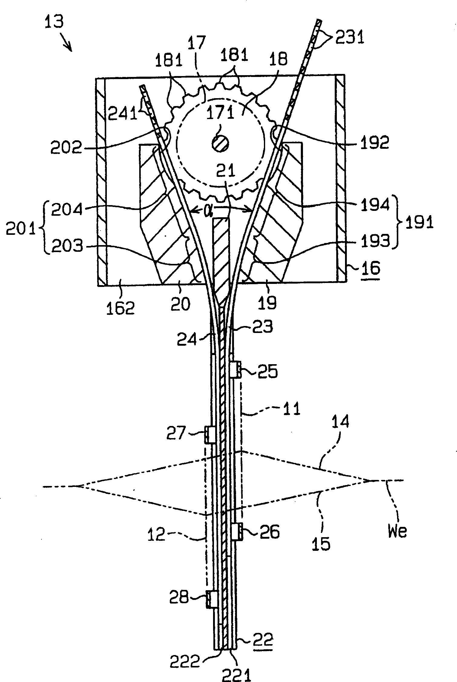
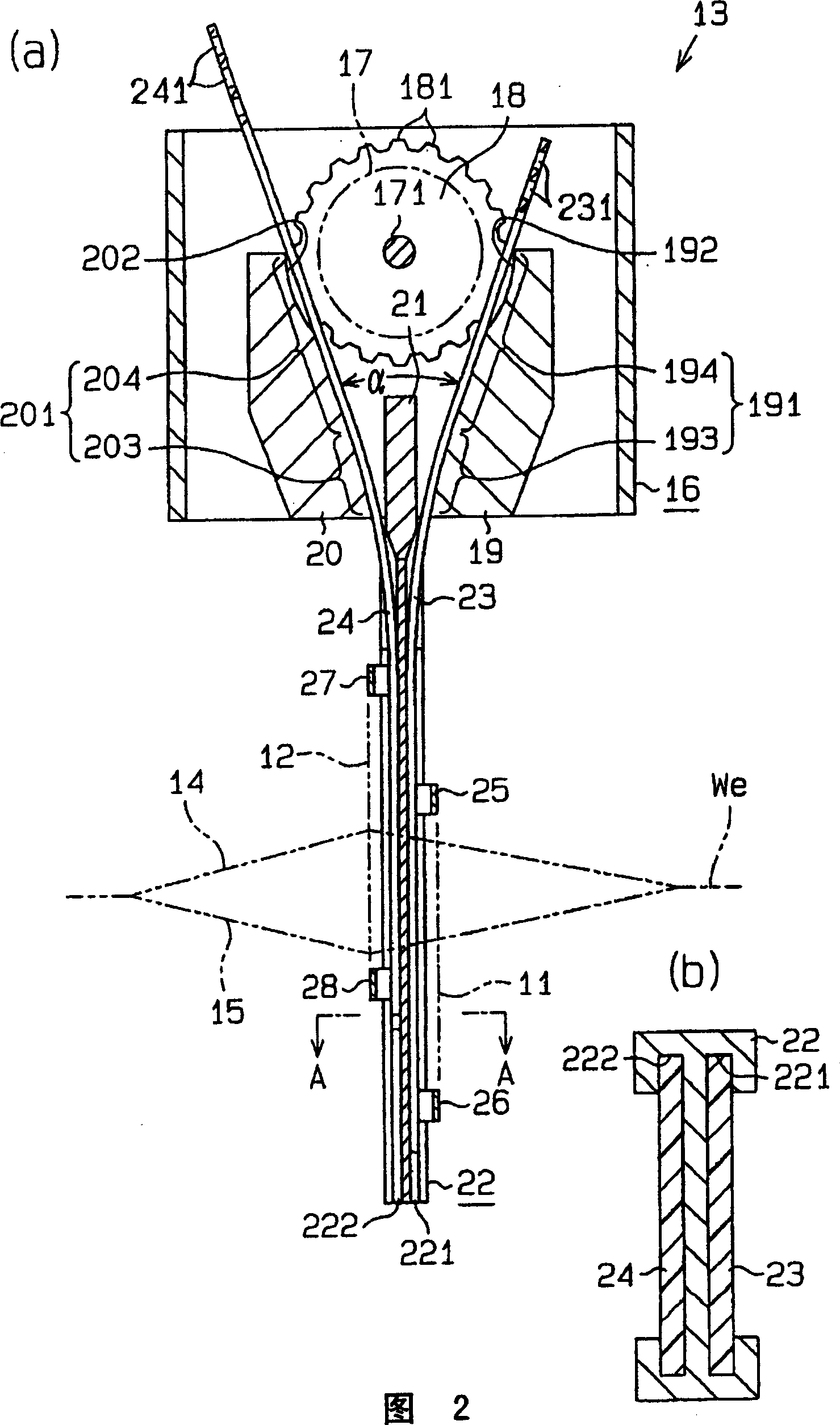
[0016] According to the first embodiment of the present invention, the device for forming the selvedge opening will refer to Figure 1-4 Describe.

[0017] Such as figure 1 As shown in and 2, the first selvedge heddle 11 and the second selvedge heddle 12 move vertically in opposite directions by the reciprocating drive mechanism 13. The movement paths for the first selvedge heddle 11 and the second selvedge heddle 12 are reciprocating paths extending vertically parallel to each other. The selvedge yarn 14 passing through the first selvedge heddle 11 and the selvedge yarn 15 passing through the second selvedge heddle 12 together with the weft introduced therethrough form a selvedge We.

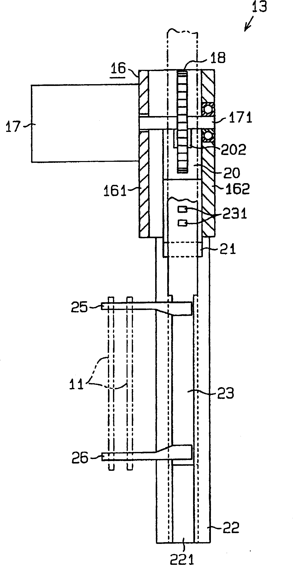
[0018] Such as image 3 with 4 As shown, the motor 17 is connected to the inner wall 161 of the box 16 constituting the reciprocating drive mechanism 13. The upper and lower parts of the box 16 are open. The output shaft 171 of the motor 17 extends through the inner wall 161 and into the box 16. T...


PUM


Abstract

The present invention provides with a list formation device which enlarges the open angle of yarn fringes without interfere the high speeding in a spinning machine. A power delivery tooth 181 of a wheel 18 is rotating by an electric motor 17 and engaging with power bearing holes 231, 234 of a first ligature 23 and a second ligature 24, respectively. An engage position between the first ligature 23 and the wheel 18 is limited by a first position regulation object 19, and the engage position between the second ligature 24 and the wheel 18 is limited by a second position regulation object 19. A part of the ligatures 23, 24 is inserting into guiding slots 221, 222 of a guiding path 22. A warp-lifting device 11 for use in a first side is supported by hooks 25, 26 of the ligature 23, and A warp-lifting device 12 for use in a second side is supported by hooks 27, 28 of the ligature 24.

Description

Technical field [0001] The present invention relates to a selvedge forming device for a loom, which is adapted to form selvedges according to the reciprocating operation of a first selvedge heddle and a second selvedge heddle in opposite directions. Background technique [0002] For example, Patent Document JP10-503563A discloses a selvedge forming device, which is adapted to form selvedges according to the reciprocating operation of the first selvedge heddle and the second selvedge heddle in opposite directions. In the selvedge forming device disclosed in the above publication, the two-dimensional crank mechanism is driven by a motor, and a pair of yarn guide members are driven by the two-dimensional crank mechanism to cause linear reciprocating motion. The two-dimensional crank mechanism includes a lever mounted on the output shaft of the motor and a pair of connecting rods connected to the lever. The pair of connecting rods are connected correspondingly to the pair of guide me...

Claims


Application Information

Patent Timeline
IPC IPC(8): D03D47/44D03C11/00D03D47/40
CPCD03C11/00B42F1/02B42P2201/08B42P2221/06B42P2221/08B42P2221/10G09F23/00
Inventor 石川洋彦金原雅彦
Owner TOYOTA IND CORP
Why Eureka
Try Eureka