
Biotic plate propoller ship for

A thruster, flat plate technology, applied in the direction of non-rotating propulsion elements, etc., can solve the problems of no Weis-Fogh effect and no good continuity of motion, and achieve the effects of small wake, simple manufacturing and high efficiency

Inactive Publication Date: 2004-10-20
ANHUI UNIVERSITY OF TECHNOLOGY
View PDF3 Cites 31 Cited by
  • Summary
  • Abstract
  • Description
  • Claims
  • Application Information

AI Technical Summary

Problems solved by technology

U.S. Patent 4,102,293 and the Chinese patent application No. 02133483.8 propose a new device for propelling ships that actually utilizes the Weis-Fogh effect; but these propulsion devices all make the blades swing back and forth, and the motion does not have good continuity, and A set of motion conversion mechanism is also needed between the commonly used rotating engine
Although the Chinese patent application with the application number 97101346.2 proposes a continuously rotating paddle board, it only produces paddle-like strokes and does not have the function of Weis-Fogh effect

Method used


Image

  • Biotic plate propoller ship for
  • Biotic plate propoller ship for
  • Biotic plate propoller ship for

Examples


Embodiment Construction

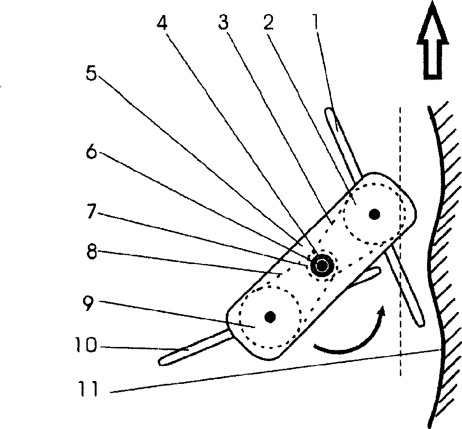
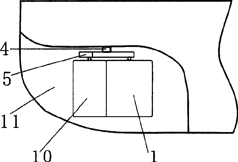
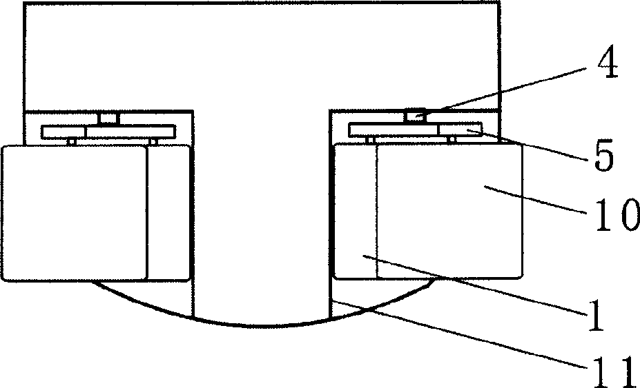
[0014] Such as figure 1 As shown, the bionic flat plate ship propeller of the present invention mainly consists of: the rotating arm shaft 4, the rotating arm 5, the flat blades 1 and 10, the fixed wheel shaft 6 inside the fixed wall 11 and the rotating arm 5, the fixed wheel 7, the transmission chain 3 and 8, moving wheel 2 and 9 form. The fixed wall 11 is a part of the hull, at the bottom of the stern, the direction is parallel to the longitudinal symmetrical plane of the hull, the fixed wall 11 here is made into a curved surface according to the motion track of the edge of the flat paddle 1 or 10, and a simple plane shape can also be adopted, such as image 3 shown. The pivoting arm shaft 4 is perpendicular to the plane of the ship deck and is installed near the fixed wall 11. The distance between the pivoting arm shaft 4 and the fixed wall 11 should make the edges of the flat blades 1 and 10 very close to the fixed wall 11 but not touch the fixed wall 11 when rotating. T...


PUM


Abstract

A bionic flat propulsion mechanism ship is composed of two units which are left-right symmetrical relative to the longitudinal axis of ship and respectively installed at left and right of hull bottom at ship tail. Each unit consists of fixed wall, rotary arm and its axle, and two paddles. When the paddles are rotating, a bionic Weist-Fogh effect is generated between paddle and wall for increasing its propulsion efficiency.

Description

Technical field: [0001] The invention belongs to the technical field of ship machinery and bionic machinery, and in particular relates to a bionic flat-plate ship propeller capable of producing bionic Weis-Fogh effect. Background technique: [0002] The Weis-Fogh effect is a mechanism discovered by the British biologist Weis-Fogh.T to generate a large lift when flying. The key to this mechanism is a "sumo and jerk" movement of the insect's wings. The process of sumo means that when the wings are approaching behind them, they rotate and close together with the front edge of the wings as the axis, and at this time, the air between the wings is squeezed out downward. The rapid expansion process refers to the rapid rotation and opening of the wings from the closed state with the rear edge as the axis. At this time, a low-pressure area is formed between the wings, and the outside air rushes in from the upper part. [0003] At home and abroad, more attention is paid to the practi...

Claims


Application Information

Patent Timeline
Patent Type & Authority Applications(China)
IPC IPC(8): B63H1/36
Inventor 邱支振邱晗
Owner ANHUI UNIVERSITY OF TECHNOLOGY
Learn More