
Servo driving device and bionic fish using servo driving device

A servo drive device and bionic fish technology, applied in the field of bionic fish, can solve the problems of insufficient energy, difficult steering, inconvenient communication with the main station, etc., and achieve the effects of flexible manipulation and energy saving.

Pending Publication Date: 2020-12-22
SHENZHEN KUANG CHI SPACE TECH CO LTD
View PDF0 Cites 1 Cited by
  • Summary
  • Abstract
  • Description
  • Claims
  • Application Information

AI Technical Summary

Problems solved by technology

In the current field of bionic fish technology for deep-sea fish, when bionic fish is operating at sea, there are often problems such as insufficient energy, difficulty in turning, and inconvenient communication with the main station.

Method used


Image

  • Servo driving device and bionic fish using servo driving device
  • Servo driving device and bionic fish using servo driving device
  • Servo driving device and bionic fish using servo driving device

Examples


Embodiment 1

[0049] A servo drive device, comprising a control host, a microcontroller, a radio transmitter, artificial muscles, a first servo motor, and a second servo motor electrically connected, the servo drive device is controlled by the control host, and the control host sends The signal is transmitted to the BLE link transceiver wirelessly to the floating station, the BLE link of the floating station receives the signal and transmits it to the microcontroller, and the data of the microcontroller is transmitted to the base station. The artificial muscle includes biometal fibers. The microcontroller is arranged on the top of the bionic fish head. The radio transmitter is arranged on the side of the bionic fish head. The artificial muscles are arranged on the fins of the bionic fish. The bionic fish fins include pectoral fins, dorsal fins, anal fins and caudal fins. The first servo motor is arranged on the middle side of the pectoral fin and tail fin. The second servo motor is loca...

Embodiment 2

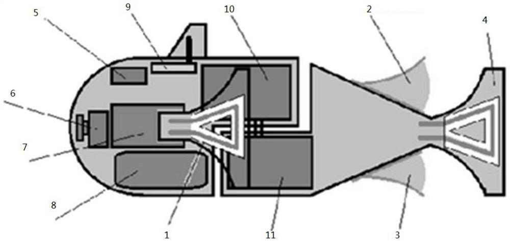
[0054] figure 2 It is a structural schematic diagram of the bionic fish of the present invention. From figure 2 It can be seen from the figure that the two servo motors are installed at a "joint" in the middle part of the body, and the "joint" is in the middle of the tail fin and two pectoral fins of the bionic fish. Two servo motors are placed on both sides of the caudal fin and pectoral fin respectively. The caudal, pectoral, dorsal, and anal fins attached to the body parts of the bionic fish are all powered by artificial muscles. Due to the use of two servo motors, the maximum angular velocity and angular range of the bionic fish in the joints are twice that of the single-motor bionic fish. This oscillating mechanism is similar to two rotary actuators, namely servo motors. The drive of the servo motor is transmitted through the connecting rod. This mechanism helps simulate real fish propulsion movements.

[0055] This study compared the movement of a bionic fish usi...


PUM


Abstract

The invention provides a servo driving device and a bionic fish using the servo driving device. The servo driving device comprises a control host, a microcontroller, a radio transmitter, artificial muscles, a first servo motor and a second servo motor which are electrically connected, and the servo driving device is controlled by the control host. The control host sends a signal to a BLE link transceiver and wirelessly transmits the signal to a floating station, the BLE link of the floating station receives the signal and transmits the signal to the microcontroller, and data of the microcontroller is transmitted to the base station. A novel underwater robot integrating bionics and a servo motor driving mode can meet the requirements of human beings for marine monitoring and investigation task diversity in the future; when an operation task needs long-distance navigation or long-time sequence in-place work, a bionic mode is adopted, the buoyancy is changed by changing the drainage volume of the bionic mode, the posture is changed by adjusting the position of the internal ballast mass, efficient gliding motion is achieved through the fins, and energy is effectively saved.

Description

【Technical field】 [0001] The invention relates to the technical field of bionic fish, in particular to a servo drive device and a bionic fish using the device. 【Background technique】 [0002] With the development of science and technology, human needs for the diversity of marine monitoring and survey tasks are also increasing. When the operation task requires long-distance navigation or long-term on-site work, the bionic mode is adopted. In this mode, the buoyancy is changed by changing the displacement volume of the self, and the attitude is changed by adjusting the position of the internal ballast mass, and realized by fins. Efficient gliding movement is very necessary. In the field of bionic fish technology for deep-sea fish, when bionic fish operates at sea, there are often problems such as insufficient energy, difficulty in turning, and inconvenient communication with the main station. 【Content of invention】 [0003] The technical problem to be solved by the present...

Claims


Application Information

Patent Timeline
Patent Type & Authority Applications(China)
IPC IPC(8): B63C11/52B63G8/22B63G8/16B63H1/36B63H21/17
CPCB63C11/52B63G8/22B63G8/16B63H1/36B63H21/17
Inventor 张美莹季春霖姜定琴
Owner SHENZHEN KUANG CHI SPACE TECH CO LTD
Learn More