
Plate blade thrusting unit for flying vehicle

A technology for a thrust device and an aircraft, which is applied in the aviation field, can solve the problems of adverse effects on the safety and efficiency of the aircraft, difficult processing and manufacturing, and large resistance of the aircraft, and achieves the effects of simple structure, high safety and maneuverability, and flexible maneuvering.

Inactive Publication Date: 2008-08-27
王志成
View PDF0 Cites 5 Cited by
  • Summary
  • Abstract
  • Description
  • Claims
  • Application Information

AI Technical Summary

Problems solved by technology

The traditional propeller has several disadvantages. First, it produces twisted airflow, which has an adverse effect on the safety and efficiency of the aircraft. Second, its large windward area creates greater resistance to the aircraft. Third, it is a curved surface, which is difficult to manufacture. Big
Although the other two thrusters are highly efficient, their structures are too complex

Method used


Image

  • Plate blade thrusting unit for flying vehicle
  • Plate blade thrusting unit for flying vehicle
  • Plate blade thrusting unit for flying vehicle

Examples


Embodiment Construction

[0013] The structural principle and working principle of the present invention will be described in detail below in conjunction with the accompanying drawings.

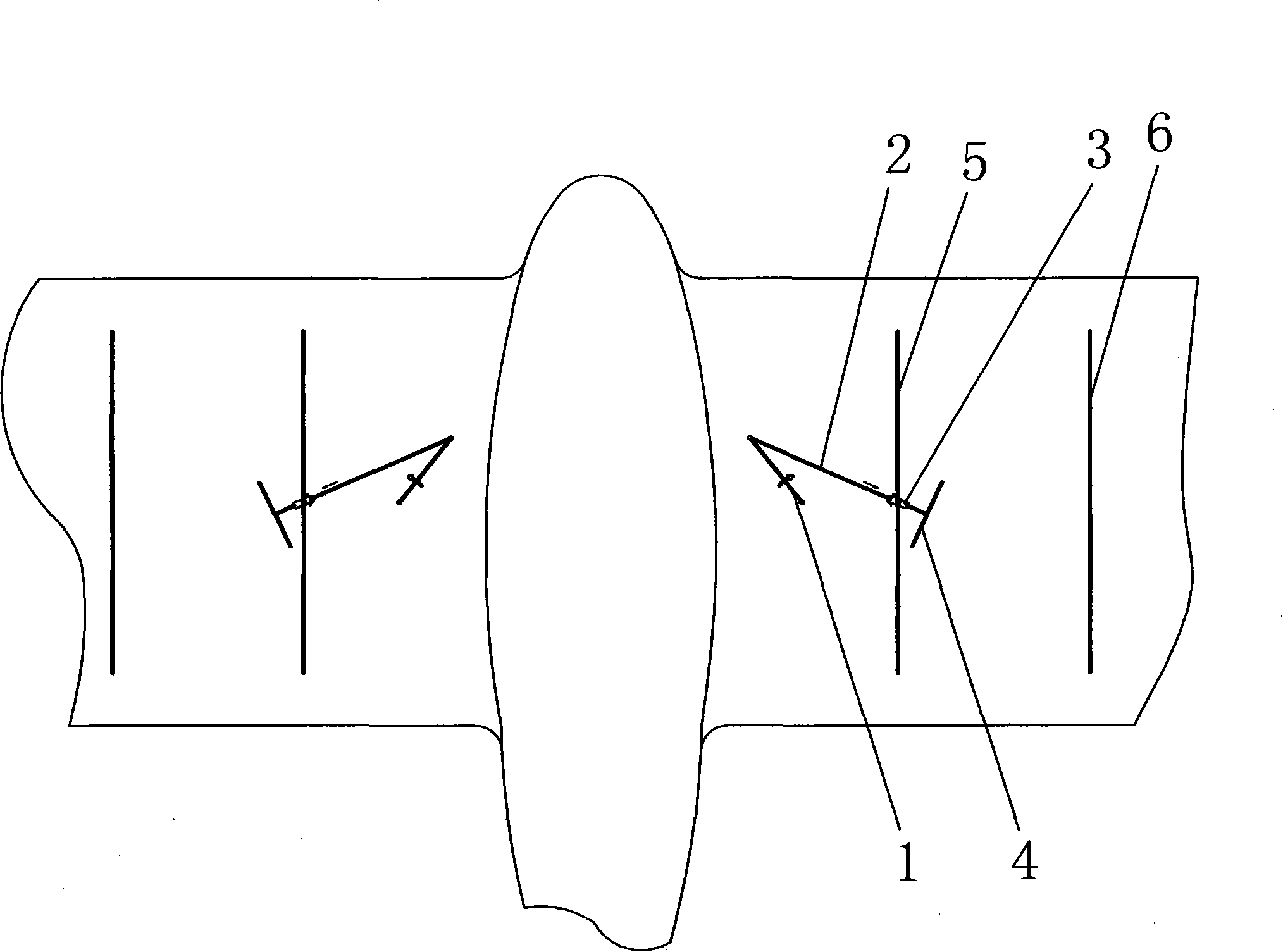
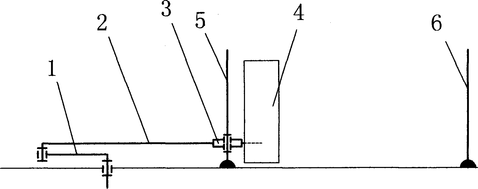
[0014] refer to figure 1 , figure 2 , image 3 and Figure 4 , the flat plate blade thrust device for aircraft of the present invention has two identical parts that are left and right symmetrical relative to the longitudinal symmetry plane of the aircraft, and are installed on the upper surface of the left and right wings of the aircraft respectively, and each part is guided by a crank 1, a connecting rod 2, and a connecting rod. One end of the connecting rod 2 is vertically fixed to the lower middle position of the flat blade 4, and the other end of the connecting rod 2 passes through the connecting rod guide 3 and the crank 1 is connected, the connecting rod guide 3 is loosely installed in the middle position of the lower part of the inner fixed plate 5, the vertical center axis of the connecting rod guide 3 is ...


PUM


Abstract

The invention relates to a plate blade propulsion unit for an aerial vehicle, which is provided with two same portions which are bilaterally symmetrical relatively to the longitudinal symmetrical plane of the aerial vehicle and respectively mounted on the upper surfaces of the left wing and the right wing of the aerial vehicle, and each portion is composed of a crank, a connecting bar, a connecting bar guide, a plate blade, an inner side fixing plate and an outer side fixing plate. Motor drive is transmitted to the crank by a reducer casing, one end of the connecting bar does circular motion under traction of the crank, the other end does closed curvilinear motion similar to the profile of 'human ears', the middle of the connecting bar slides reciprocally in the connecting bar guide, the plate blades do motion constantly and reciprocally 'flap and unfolding' similar to an insect on the upper surfaces of wings and between the inner side fixing plate and the outer side fixing plate under drive of the connecting bar, thereby Weis-Fogh effect is produced to propel a an aerial vehicle to fly. The plate blade propulsion unit for an aerial vehicle has simple structure, high efficiency and safety.

Description

technical field [0001] The invention relates to a flat plate blade thrust device for an aircraft, which belongs to the field of aviation technology. Background technique [0002] At present, the propulsion device of aircraft mainly has three forms: propeller, turbine and jet engine. The traditional propeller has several disadvantages. First, it produces twisted airflow, which has an adverse effect on the safety and efficiency of the aircraft. Second, it has a large windward area, which produces greater resistance to the aircraft. Third, it is a curved surface, which is difficult to manufacture. Big. Although other two kinds of thrusters have high efficiency, their structures are too complicated. Contents of the invention [0003] The purpose of the present invention is to provide a flat blade propulsion device for an aircraft, which is driven by the engine through a set of mechanisms to generate the Weis-Fogh effect under the joint action of the fixed flat and flat blade...

Claims


Application Information

Patent Timeline
Patent Type & Authority Applications(China)
IPC IPC(8): B64C39/00
Inventor 王志成
Owner 王志成
Learn More