
Low voltage largecurrent modle power source

A modular power supply and high current technology, applied in electrical components, adjusting electrical variables, converting DC power input to DC power output, etc., can solve problems such as difficulty in obtaining efficiency, low utilization rate, and inability to meet high power output

Inactive Publication Date: 2004-10-20
ZTE CORP
View PDF0 Cites 16 Cited by
  • Summary
  • Abstract
  • Description
  • Claims
  • Application Information

AI Technical Summary

Problems solved by technology

The traditional module power supply uses a single stage to realize DC / DC conversion, which has certain advantages in terms of cost, but the same topology is difficult to meet the requirements of wide range input and output, especially in the case of low voltage and high current output, it is difficult to obtain sufficient efficiency
Moreover, the working state of the magnetic core is greatly affected by the input and output voltages, and it is difficult to optimize the design
Under normal circumstances, the utilization rate is not high, and relatively high efficiency can only be obtained in a certain range; in the case of low-voltage and high-current output, the use of synchronous rectification technology requires complex drive circuits to obtain stable drive pulses; due to the size of the module However, the effective window cross-sectional area of ​​a single magnetic core cannot meet the requirements of higher power output

Method used


Image

  • Low voltage largecurrent modle power source
  • Low voltage largecurrent modle power source
  • Low voltage largecurrent modle power source

Examples


Embodiment Construction

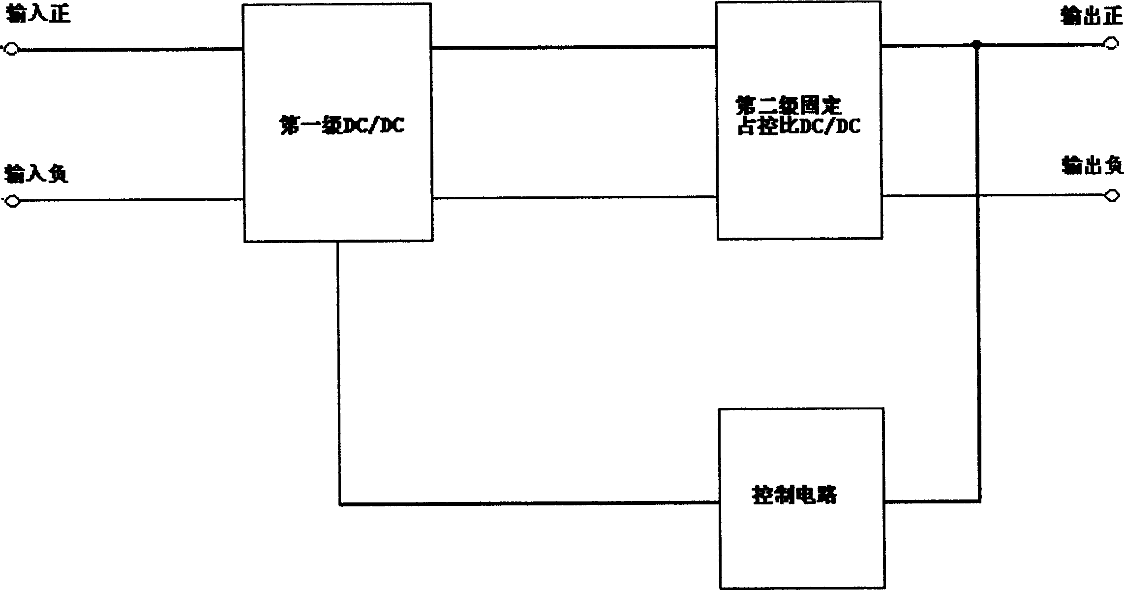
[0016] figure 1 It is a functional block diagram of the first scheme of the present invention. exist figure 1 Among them, the input voltage is converted by the first stage DC / DC, which is controlled by the control circuit to output a stable DC voltage to the second stage fixed duty ratio DC / DC conversion unit. Due to the use of fixed duty ratio control , the control pulse is provided by the control power, and the output can obtain a stable DC.

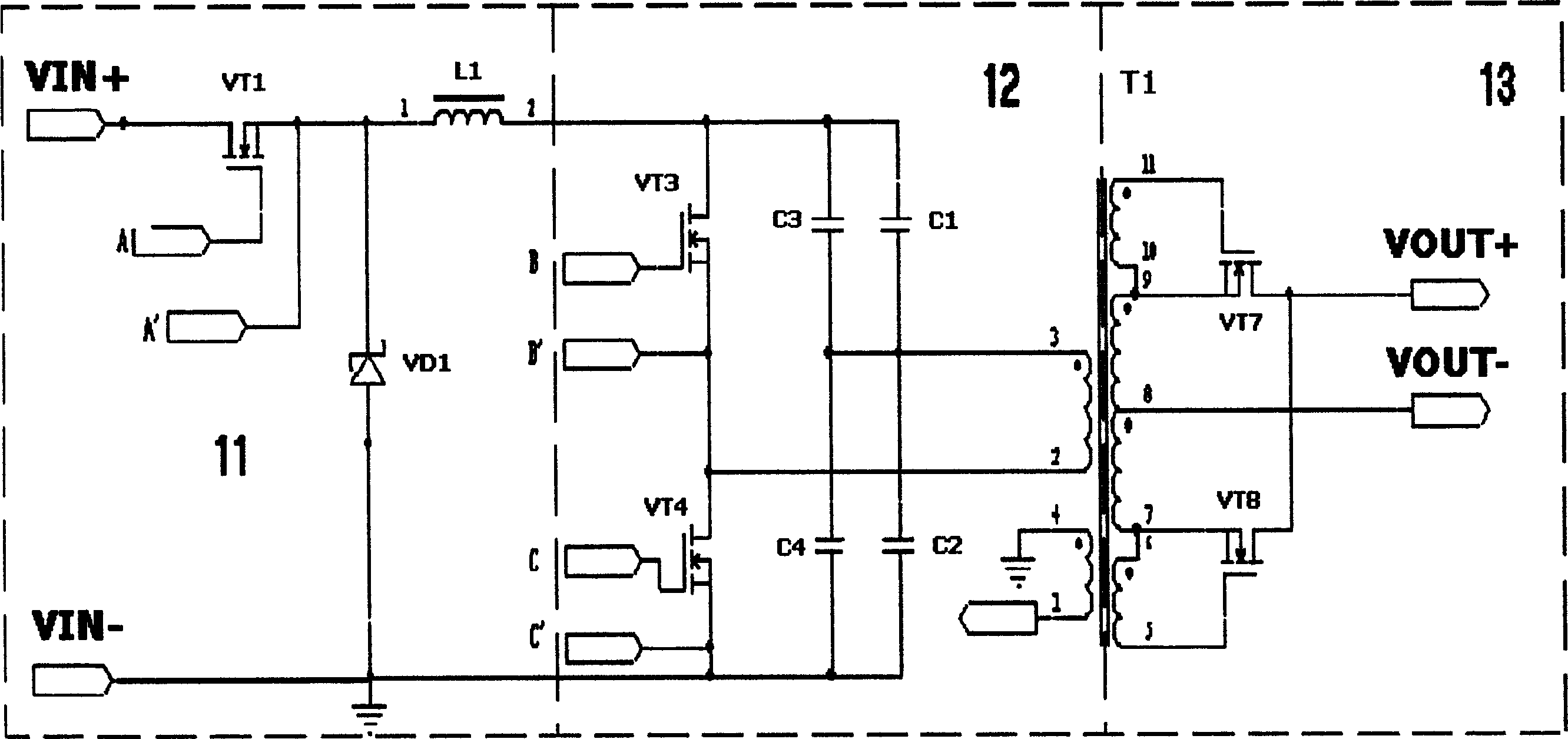
[0017] figure 2 It is a specific circuit diagram of an embodiment of the first stage DC / DC and the second stage fixed duty ratio DC / DC conversion unit in the first solution of the present invention. exist figure 2 Among them, a non-isolated buck circuit 11 is used to realize the function of the first-stage DC / DC conversion unit, and a half-bridge circuit 12 with high conversion efficiency and a synchronous rectification circuit 13 are used to realize the second-stage fixed duty cycle DC / DC The function of the conversion unit: th...


PUM


Abstract

Power source module includes first stage DC / DC converter unit converts variable input DC voltage to stable DC output; second stage DC / DC converter unit with fixed duty ratio; control circuit controls output from first stage DC / DC converter unit, and provides driving pulse for second stage DC / DC converter unit with fixed duty ratio. The invented power source provides input voltage in wide range. Synchronous rectified drive signal with stable amplitude can be obtained through second stage DC / DC isolating transformer with fixed duty ratio. The said drive signal can drive synchronous rectification tube directly so as to realize synchronous rectification output. The invention is applicable to power source module in low voltage and large current in high efficiency.

Description

technical field [0001] The invention relates to a module power supply, in particular to a module power supply using a switching converter. Background technique [0002] With the development of electronic technology, the continuous improvement of VLSI integration, and the increasing complexity of the system, the demand for power supplies is becoming more and more compact, general-purpose, low-voltage, and high-power density. The traditional modular power supply uses a single stage to achieve DC / DC conversion, which has certain advantages in terms of cost, but the same topology is difficult to meet the requirements of wide range input and output, especially in the case of low voltage and high current output, it is difficult to obtain sufficient efficiency. Moreover, the working state of the magnetic core is greatly affected by the input and output voltages, making it difficult to optimize the design. Under normal circumstances, the utilization rate is not high, and relatively...

Claims


Application Information

Patent Timeline
IPC IPC(8): H02M3/00
Inventor 樊晓东甘旭
Owner ZTE CORP
Learn More