Cylinder cap structure

A technology of cylinder head and cylinder block, applied in the direction of cylinder head, cylinder, jet propulsion device, etc., can solve the problems of inability to spread oil flow and leakage flow, increase of oil consumption, and deterioration of exhaust gas, etc. The effect of smooth supply, prevention of deterioration of exhaust gas, and prevention of deterioration of lubricating oil

Active Publication Date: 2004-10-27
MITSUBISHI MOTORS CORP
View PDF1 Cites 11 Cited by
  • Summary
  • Abstract
  • Description
  • Claims
  • Application Information

AI Technical Summary

Problems solved by technology

Therefore, the blow-by air blown upward from the cylinder block hinders the flow of oil into the oil pan 6, and causes the following problems: the oil 10 does not fall down into the oil pan; and the oil excessively collects in the rocker chamber. bottom surface
However, this prior art structure does not allow the lubricating oil flow and the blow-by flow to spread out
Also, this structure does not take measures to prevent the increase of oil quantity (occurring in four-valve engine) and prevent the increase of blow-by quantity (caused by obtaining higher output)
Therefore, it becomes the main cause of deterioration of exhaust gas and increase of lubricating oil consumption

Method used


Image

  • Cylinder cap structure
  • Cylinder cap structure
  • Cylinder cap structure

Examples


Embodiment Construction

[0028] Embodiments of the present invention will be described in detail below with reference to the accompanying drawings.

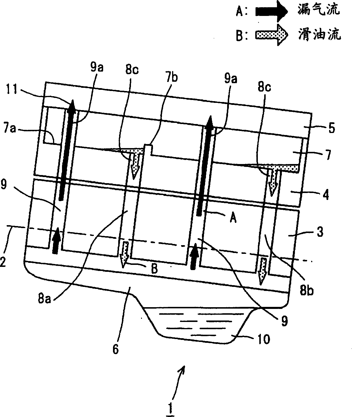
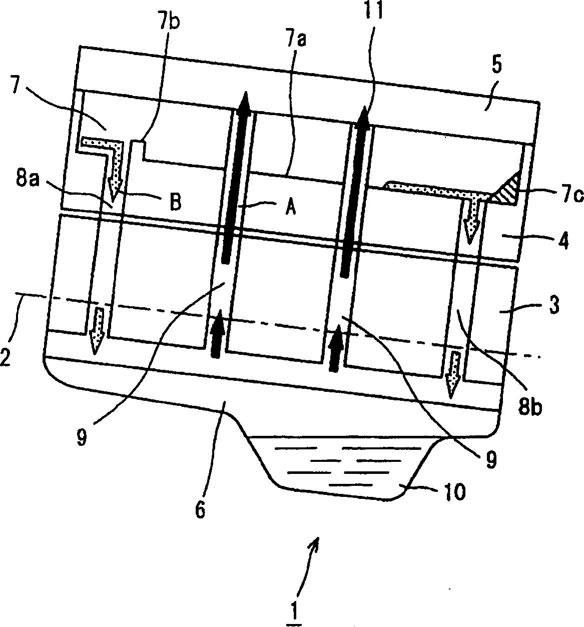
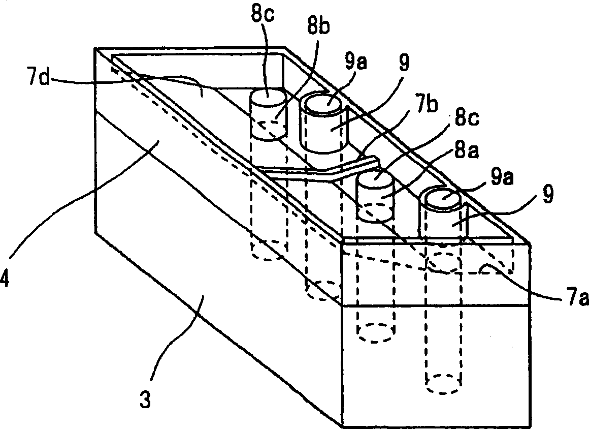
[0029] figure 1 A schematic diagram of an engine having a cylinder head structure according to an embodiment of the present invention is shown. image 3 A perspective view of an engine having a cylinder head structure of an embodiment of the present invention is shown.

[0030] The engine 1 is tilted in the direction of the crankshaft 2 (eg figure 1 As shown in , engine 1 is tilted down to the right). The oil collecting passages 8a and 8b and the blow-by air passage 9 are respectively arranged on the left or right side of the crankshaft 2 in the bottom surface portion 7a of the rocker chamber.

[0031] The engine 1 comprises a cylinder block 3 having cylinders in which pistons are slidably received, and a cylinder head 4 provided with a valve mechanism (not shown) for driving the suction Gas valve and exhaust valve. A cylinder head 4 is arranged o...


PUM


Abstract

To provide a cylinder head structure smoothening the flow of oil and blowby gas which are deteriorated at the time of making an engine for a vehicle into a direct-injection multiple valve type. In the engine 1 for the vehicle mounted being inclined in a direction of a crankshaft 2, a weir is provided in an inclined lower side of an oil recovery passage 8a other than an inclined lower end in a lower surface 7a of a locker chamber in a cylinder head 4. An inclined surface 7c is provided in the inclined lower side of an oil recovery passage 8b positioned in a lowermost part, or an inclined surface 7d is provided in one side with no oil recovery passage 8 toward the oil recovery passage. An upper part 9a of a hole of a blowby gas passage 9 is formed to be higher than the lower surface 7a of the locker chamber. (C)2005,JPO&NCIPI.

Description

technical field [0001] The invention relates to a cylinder head structure of an automobile engine. Background technique [0002] There are many types of automotive engines and they come in a wide range of constructions. However, car engines have the same basic structure. The constituent elements of the engine can be divided into an engine body and engine accessories such as a cooling unit and a fuel system. The engine block includes the cylinder head and the cylinder block. [0003] In a car engine, there are many sliding parts, such as pistons and cylinders, and many rotating parts, such as the crankshaft. A large amount of lubricating oil is circulated all the way to the parts where these metal parts come into contact with each other, thereby reducing friction. [0004] Also, during the compression and combustion strokes of the engine, combustion chamber gases enter the crank chamber through the gap between the piston (or piston rings) and the cylinder wall. This gas ...

Claims


Application Information

Patent Timeline
Patent Type & Authority Applications(China)
IPC IPC(8): F01M1/06F01M11/02F01M11/06F01M13/00F02F1/24F02F1/40
CPCF01M11/02F02F1/40F01M11/064F01M2011/023F01M13/0416
Inventor 田中多闻
Owner MITSUBISHI MOTORS CORP
Why Eureka
Try Eureka