
Apparatus for drying a paper web

A technology of drying and drying drums, which is applied in the direction of dryers, papermaking, paper machines, etc., and can solve the problems of not having enough space for use

Inactive Publication Date: 2004-11-03
ANDRITZ AG
View PDF0 Cites 11 Cited by
  • Summary
  • Abstract
  • Description
  • Claims
  • Application Information

AI Technical Summary

Problems solved by technology

However, especially in the retrofitting of existing installations, also in new installations, there is often not enough space available for this

Method used


Image

  • Apparatus for drying a paper web
  • Apparatus for drying a paper web
  • Apparatus for drying a paper web

Examples


Embodiment Construction

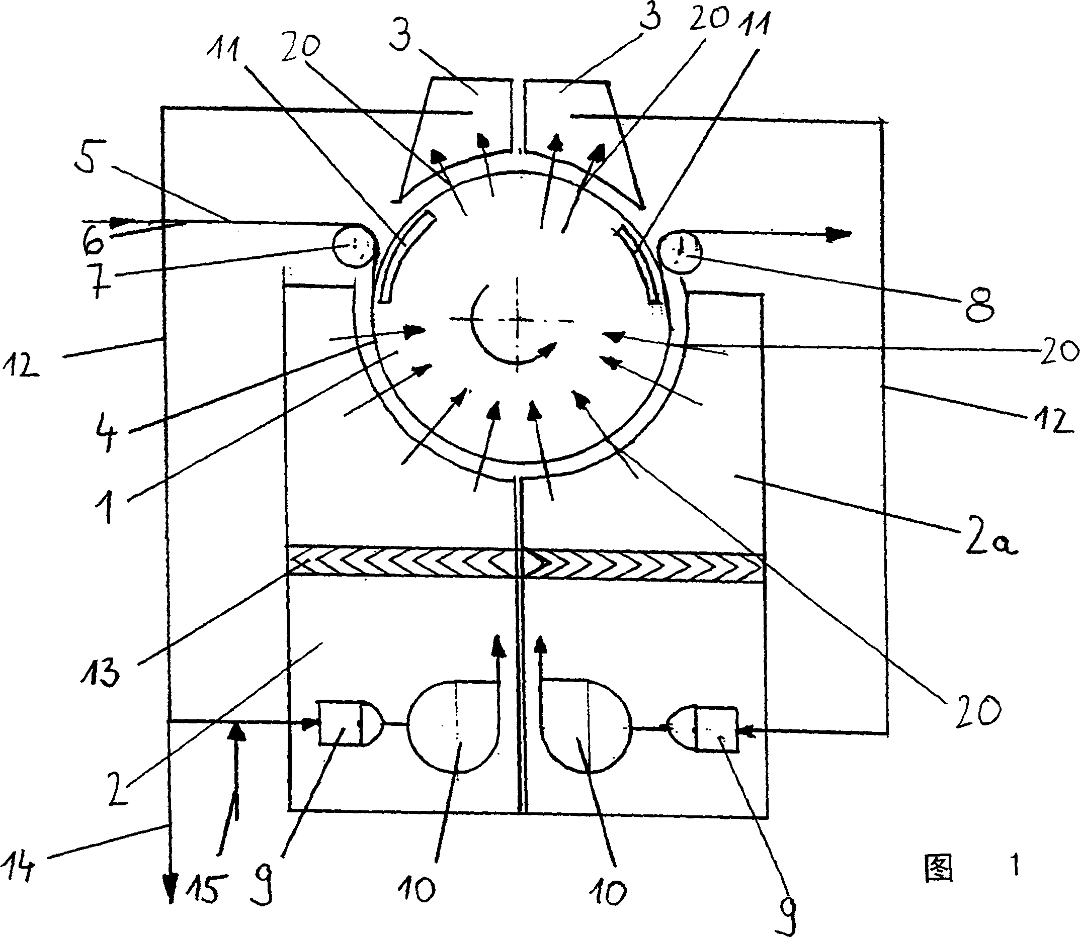
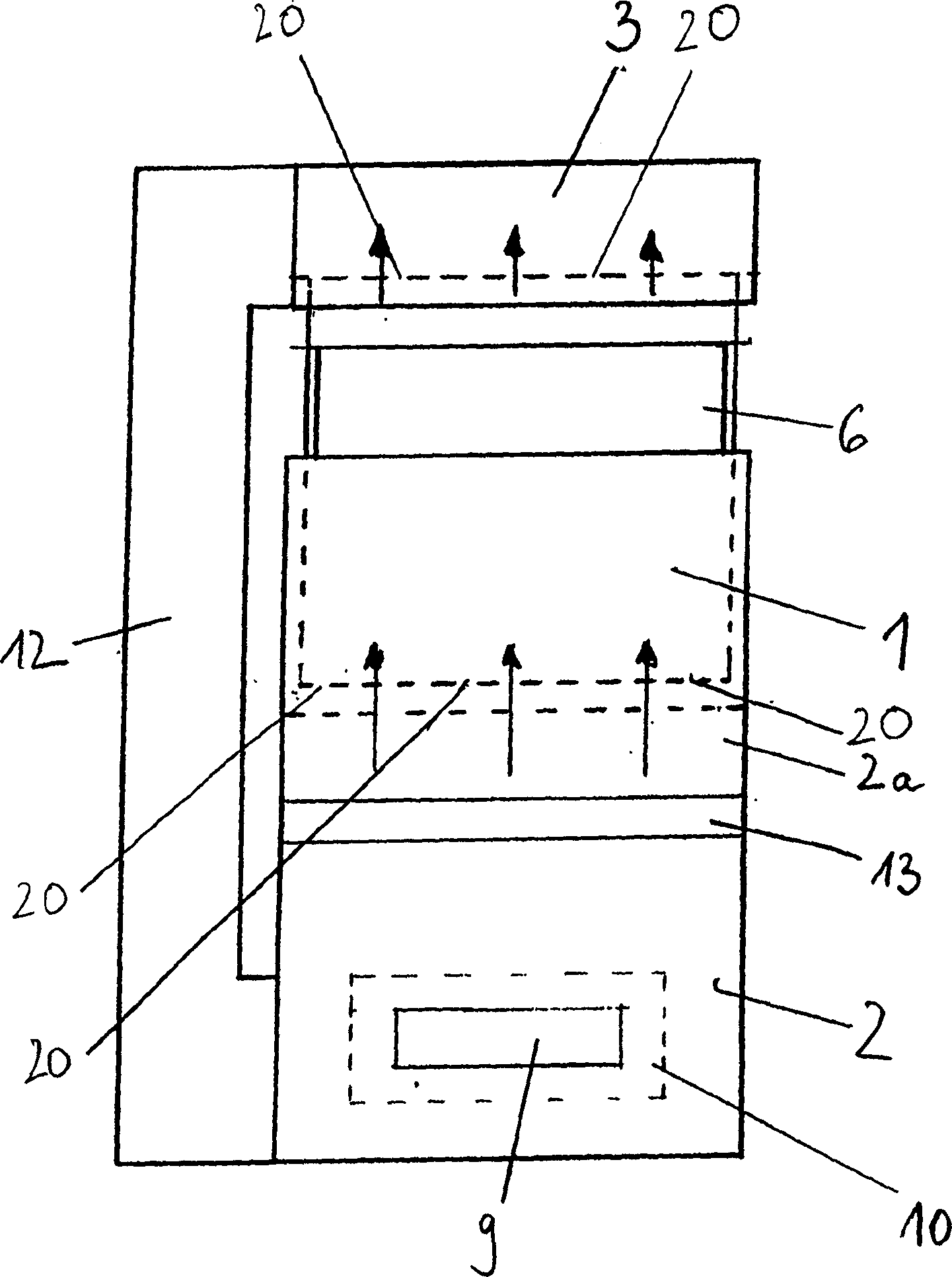
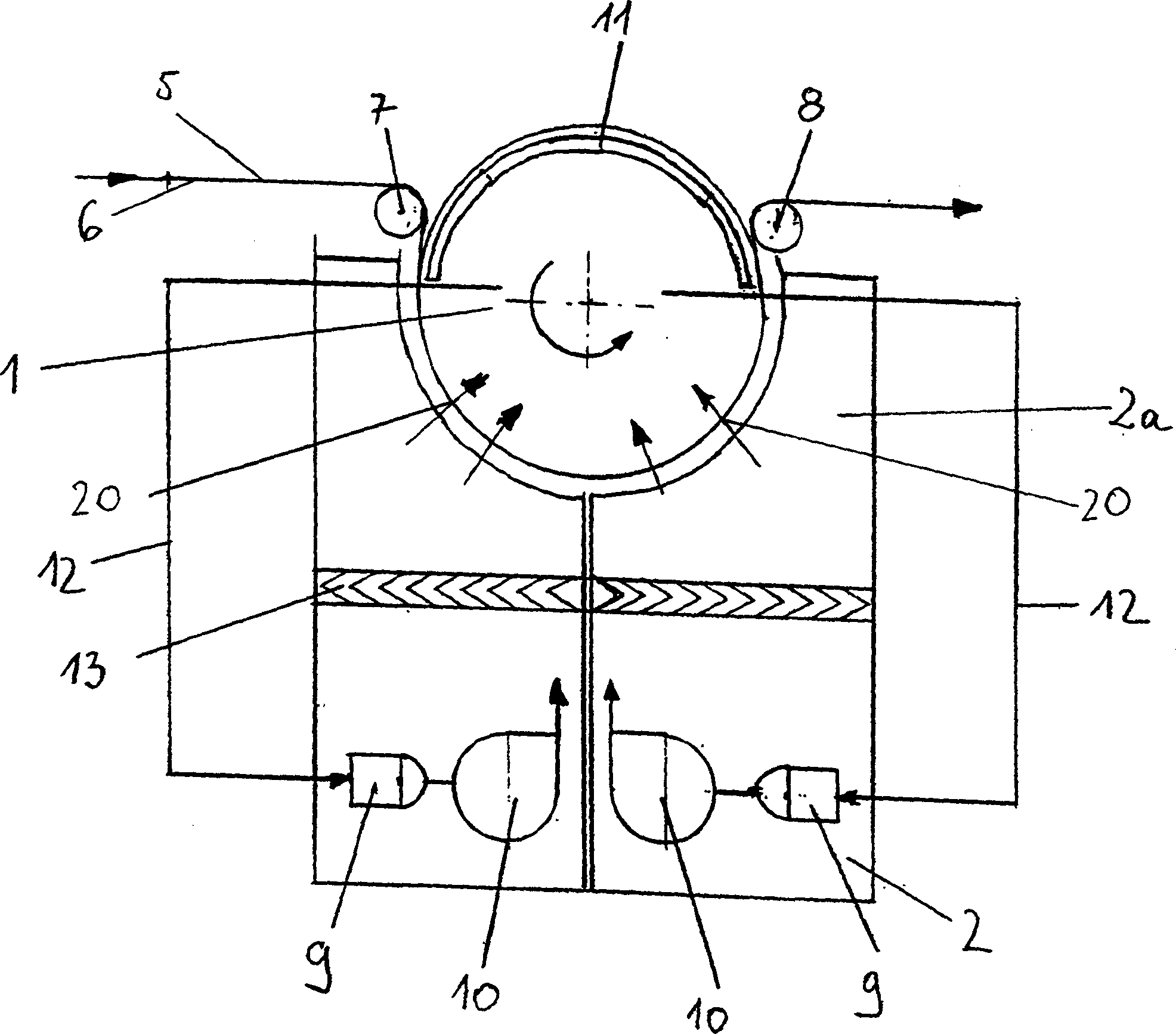
[0016] Figure 1 shows a schematic sectional view of a first embodiment of the invention, in which a drying drum 1 is largely surrounded by a shell comprising two parts. The first part of the housing is formed by a lower hood 2 partially surrounding the cylindrical wall 4 of the drying drum 1 . The second part of the housing is formed by a suction hood 3 which also partially surrounds the cylindrical wall of the drying drum. The paper web 5 to be dried is carried onto the drying drum 1 by the drying fabric running on the deflection roll 7 and is taken away from the drying drum 1 again on the deflection roll 8 after the drying process, the paper web 5 rotates around the counterclockwise direction. Winding on part of the cylindrical wall 4.

[0017] The cylindrical wall 4 of the drying drum 1 is provided with a large number of orifices or openings 20, so that the hot air used to dry the paper web 5 can flow through the cylindrical wall. This hot air is generated by two heating ...


PUM


Abstract

A device for drying a paper web has a drying drum mounted at least partially inside a housing, whereby the cylinder wall of the drying drum is provided with a large number of apertures or openings so that hot air can flow through the cylinder wall, a heating device to generate hot air, a feed device to apply the hot air to the paper web, and a device to carry off the air containing moisture. In order to permit a compact design, the housing surrounds at least one hood which partly encloses a cylinder wall of the drying drum with the heating device being located inside the hood. Both the feed device and the heating device should be located preferably inside the hood.

Description

technical field [0001] The invention relates to a device for drying a paper web, which device has a drying drum mounted at least partly inside the housing, whereby the cylindrical wall of the drying drum is provided with a large number of holes or openings so that hot air can flow through the cylindrical wall; it also includes heating means for generating hot air, supply means for supplying hot air to the web, and means for taking away air containing moisture. Background technique [0002] According to the prior art, there are housings which serve to evenly distribute the flow of hot air, while the circulating air system with fans and heating means such as burners is located outside the housing. Since this type of through air dryer requires only moderate pressure but high air flow, only very large air ducts are considered. However, especially in the renovation of existing installations, but also in new installations, there is often not enough space available for this. Con...

Claims


Application Information

Patent Timeline
Patent Type & Authority Applications(China)
IPC IPC(8): D21F5/18
CPCD21F5/182
Inventor R·格雷梅尔W·莫塞K·吉辛J·鲍贝克
Owner ANDRITZ AG
Learn More