Method for testing power type LED thermal resistance and special purpose chip thereof

A technology of LED chips and special chips, which is applied in the field of accurate measurement of thermal resistance characteristics of power LED devices, can solve the problems of complicated operation, reduced R&D cost, high price, etc., so as to reduce manufacturing cost, reduce testing cost, and facilitate operation. Effect

Inactive Publication Date: 2004-11-10
FOSHAN NATIONSTAR OPTOELECTRONICS CO LTD
View PDF0 Cites 33 Cited by
  • Summary
  • Abstract
  • Description
  • Claims
  • Application Information

AI Technical Summary

Problems solved by technology

The difference between the two methods is: the direct method covers the chip of the power LED with a substance with a known emissivity coefficient. After the chip is powered on, the junction temperature is measured by radiating energy, or the chip is covered with liquid crystal. The color is used to measure the chip temperature. This method requires very expensive special test equipment. During the test process, the encapsulation material of the power LED needs to be removed. The operation is very complicated, and the removal of the encapsulation material also destroys the heat dissipation structure of the device itself. , which affects the accuracy of the test; the indirect method is also called the electrical method, which mainly uses the relationship between the forward voltage drop of the PN junction and the temperature when the constant current is driven. When measuring, first pass a small pulse detection current to the chip to measure this When the forward voltage drop of the PN junction is measured, then the chip current is changed to the normal working current. After the thermal balance is reached, the working current is changed to the same detection current as the pulse detection current amplitude and pulse width mentioned above, and the positive voltage of the PN junction is measured. According to the difference of the forward voltage drop before and after the test, combined with the relationship between the forward voltage drop and the temperature, the temperature rise of the PN junction of the chip is obtained, and the thermal resistance value of the power LED is further obtained. Although this method does not Destroy the packaging structure of the device, but its main disadvantage is that the heat loss during the current conversion process causes a large test error in the thermal resistance, and the measurement of the pulse detection current may be the transient thermal resistance, which is different from the actual situation. Furthermore, Detecting the forward voltage drop of the pulse current on the PN junction also requires special testing equipment, which is difficult to reduce the cost of research and development

Method used


Image

  • Method for testing power type LED thermal resistance and special purpose chip thereof
  • Method for testing power type LED thermal resistance and special purpose chip thereof
  • Method for testing power type LED thermal resistance and special purpose chip thereof

Examples


Embodiment Construction

[0022] The present invention will be described in further detail below.

[0023] The test method includes the following steps:

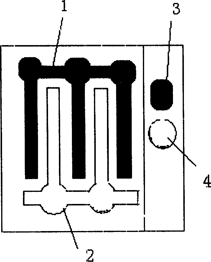
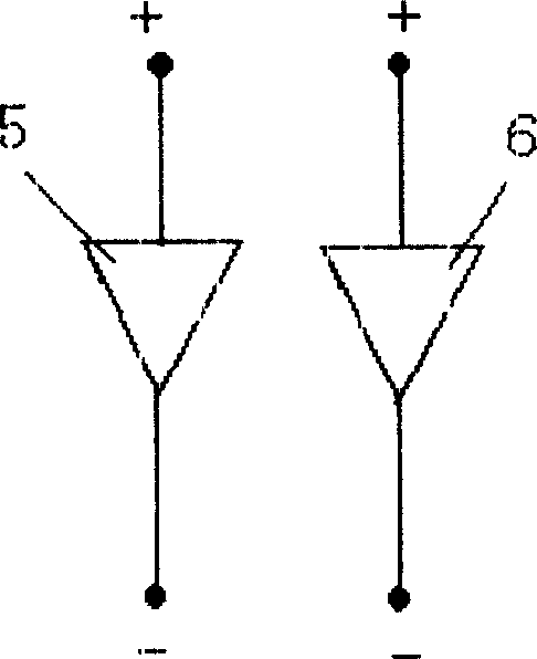
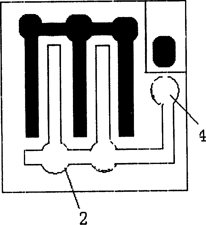
[0024] a. Manufacture a dedicated chip and integrate two LED units in the chip. The epitaxial layer and electrode layer structure of the two units are the same as the designed power LED chip, that is, the material composition, structure, and thickness of each layer are the same. It is the same as the designed power LED chip, and if the designed power LED chip has various auxiliary layers, then the dedicated chip also adds corresponding auxiliary layers. One of the two LED units is a heating unit, and the area of ​​this unit should be as close as possible to the area of ​​the designed power LED chip, in order to enable the unit to withstand higher current and to simulate as accurately as possible Heat generation of the designed power LED. The other LED unit is a detection unit. The area of ​​this unit should be as small as possible, preferably no mo...


PUM


Abstract

The invention is a method of testing thermal resistance of power LED and its special chip, its main character: using special chip to simulate the designed power LED chip, they have the same structure of extension layer and electrode layer, when using it to make the power LED to be tested, also adopting the same or similar packaging technique to the designed power LED. It can accurately simulate the thermal working characteristic of the designed power LED, by testing and calculating, obtains the thermal resistance without adopting expensive special testing instruments, reducing the development cost of power LEDs.

Description

technical field [0001] The invention relates to a technique for accurately measuring the thermal resistance characteristics of a power LED device during the process of designing or improving the power LED. Background technique [0002] Power LED, that is, power light-emitting diode, its input power is several times, tens of times, or even hundreds or even thousands of times that of ordinary LEDs. In order to dissipate the heat generated by power LEDs in a timely manner, ensure The working temperature of the power LED is within the allowable range, so that the power LED can work with high efficiency and high reliability for a long time, and the power LED device is required to have a small thermal resistance, which requires the design or improvement of the power LED package In the process of structure, packaging material, and packaging process, the thermal resistance of power LEDs is continuously measured, and the impact of new designs or improvements on thermal resistance is ...

Claims


Application Information

Patent Timeline
Patent Type & Authority Applications(China)
IPC IPC(8): G01N25/18G01R31/26H01L21/66
Inventor 李炳乾布良基王垚浩
Owner FOSHAN NATIONSTAR OPTOELECTRONICS CO LTD
Why Eureka
Try Eureka