Cascading bidirectional DC-DC converter

A DC-DC and converter technology, applied in the field of cascaded bidirectional DC-DC converters, can solve problems such as restricting applications

Inactive Publication Date: 2004-11-10
NANJING UNIV OF AERONAUTICS & ASTRONAUTICS
View PDF0 Cites 37 Cited by
  • Summary
  • Abstract
  • Description
  • Claims
  • Application Information

AI Technical Summary

Problems solved by technology

[0008] This technology uses a single-ended flyback converter as the main topology. Its main defect is that it uses a

Method used


Image

  • Cascading bidirectional DC-DC converter
  • Cascading bidirectional DC-DC converter
  • Cascading bidirectional DC-DC converter

Examples


Embodiment Construction

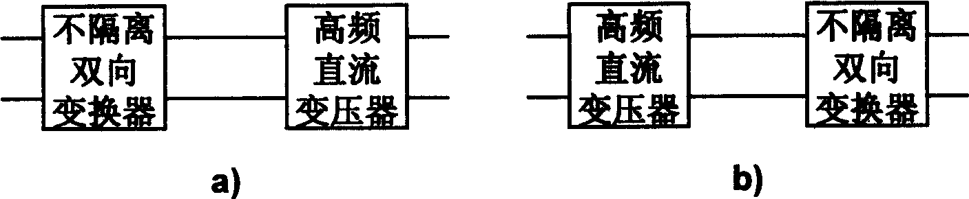
[0022] figure 1 Is the structural block diagram of the cascaded bidirectional DC-DC converter, composed of figure 1 It can be seen that the cascaded bidirectional DC-DC converter is formed by interconnecting a non-isolated bidirectional DC-DC converter and a high-frequency DC transformer. That is, the non-isolated bidirectional converter is cascaded with the high-frequency DC transformer, or conversely, the high-frequency DC transformer is cascaded with the non-isolated bidirectional converter.

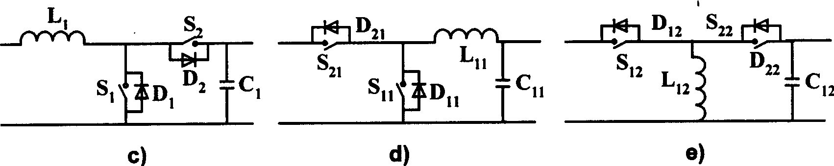
[0023] Non-isolated bidirectional DC-DC converters can be figure 2 The bidirectional boost converter shown in figure (c), the bidirectional buck converter circuit shown in figure (d), and the bidirectional buck-boost converter circuit shown in figure (e) are bidirectional conversion topologies.

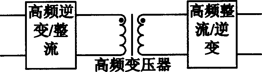
[0024] The composition of high frequency DC transformer is as follows: image 3 As shown, the high-frequency inverter / rectifier circuit is connected to the primary side of the high-freque...


PUM


Abstract

The invention relates to a cascade two-way DC-DC converter, composed of two parts: nonisolated two-way DC-DC converter and high-frequency DC transformer, where the former includes circuittopologies such as two-way boost, two-way buck, two-way boost-buck, etc. and the latter is composed of high-frequency inverter/rectifier, high-frequency transformer, and high-frequency rectifier/inverter unit, where the first and fourth ones include push-pull circuit, half-bridge circuit, full-bridge circuit, push-pull forward circuit, double-tube forward circuit, active clamped forward circuit, nonsymmetrical half-bridge circuit, and other circuits. It implements two-way energy flow and electrical isolation, where all its switch tubes are zero-voltage switches, and has the advantage of relatively independent two parts, convenience for control, high conversion efficiency and power density, and simple circuit structure, etc.

Description

technical field [0001] The cascaded bidirectional DC-DC converter of the invention belongs to a power electronic converter. Background technique [0002] There are three traditional solutions for isolated bidirectional DC-DC converters: [0003] 1. Phase-shifting bidirectional conversion technology [0004] This technology uses transformer leakage inductance (or external inductance) to complete bidirectional energy transmission through bridge arm phase shifting. It uses leakage inductance to transfer energy, limiting the application of this technology in high-power applications. [0005] 2. Voltage type-current type combined bidirectional conversion technology [0006] This technology is the combined voltage mode-current mode topology, and its main drawback is that the voltage spikes on the switching devices caused by the leakage inductance of the transformer are large. This drawback is due to the current mode topology involved in this technology, which limits the applic...

Claims


Application Information

Patent Timeline
IPC IPC(8): H02M3/22H02M3/28
CPCY02B70/1491Y02B70/10
Inventor 张方华严仰光王慧贞龚春英
Owner NANJING UNIV OF AERONAUTICS & ASTRONAUTICS
Why Eureka
Try Eureka