Method for fabricating heating element and electrode lead in carbon fiber far infrared electric heating tube

A carbon fiber far-infrared, heating element technology, applied in the direction of heating element material, heating element shape, ohmic resistance heating parts, etc., can solve the problems of easy burnout of contacts, difficult to guarantee life, difficult to control power, etc., to ensure uniform heating performance, expanding the scope of application, and ensuring the effect of service life

Inactive Publication Date: 2004-11-10
李家俊
View PDF0 Cites 6 Cited by
  • Summary
  • Abstract
  • Description
  • Claims
  • Application Information

AI Technical Summary

Problems solved by technology

This method mainly has the following disadvantages: 1. It is difficult to ensure the uniformity of the thickness of the carbon fiber felt at the current technological level, and it is also difficult to control the deviation of the shear width, which makes it difficult to control the power within the technical requirements; 2. Carbon fiber felt Uneven thickness and uneven distribution of micropores will lead to uneven heating; 3. There are great defects in the simple winding of carbon fiber felt and metal electrode leads. The contact resistance is more than 2Ω, and the contact surface load is as high as dozens of watts per square centimeter. 100 watts, the temperature is much higher than that of the heating element, the long-term energized potential difference will continue to increase, the contact is easy to burn, and the life is difficult to guarantee; 4. Due to the vapor deposition at high temperature, the carbon fiber volatiles will gradually fill the carbon fiber felt. hole, so that the resistance becomes smaller and the power increases sharply, causing the quartz tube shell of the electric heating tube to burst and damage

Method used


Image

  • Method for fabricating heating element and electrode lead in carbon fiber far infrared electric heating tube
  • Method for fabricating heating element and electrode lead in carbon fiber far infrared electric heating tube
  • Method for fabricating heating element and electrode lead in carbon fiber far infrared electric heating tube

Examples


Embodiment Construction

[0015] The steps of the present invention will be described in further detail below in conjunction with the accompanying drawings.

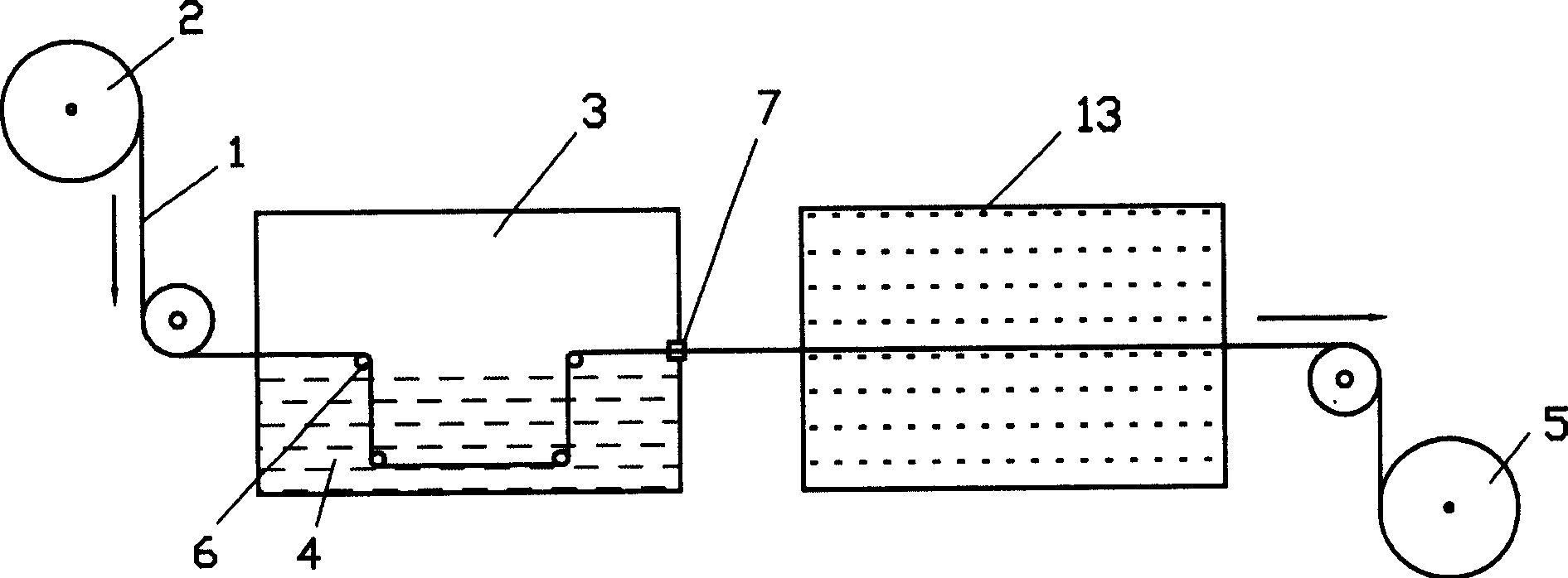
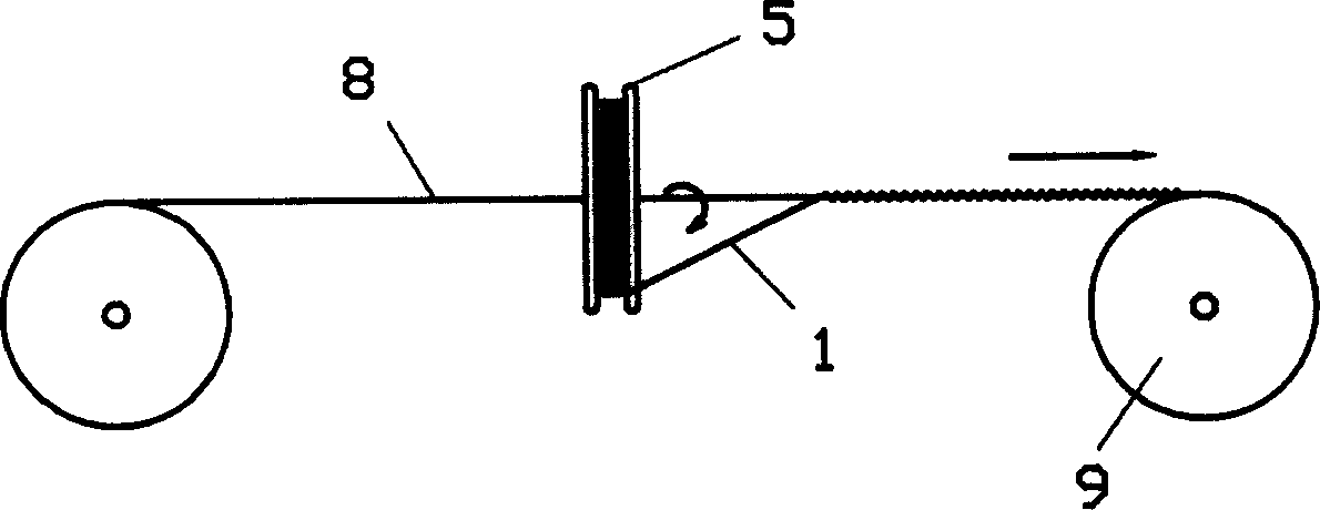
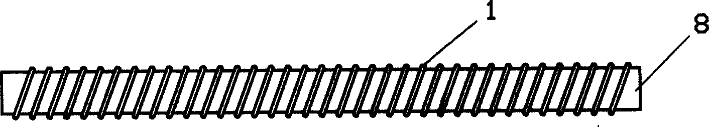
[0016] a. Coating water-soluble resin melamine formaldehyde on the carbon fiber bundle formed by gathering carbon fiber monofilaments. The carbon fiber bundle formed by gathering a plurality of carbon fiber monofilaments in this step can be purchased directly from the market, and generally thousands of them form a bundle. If the count of the purchased carbon fiber bundles is not enough, you can also gather the purchased carbon fiber bundles into one bundle. The water-soluble resin melamine formaldehyde acts as a bond protection to prevent the carbon fiber bundles from breaking or fluffing during subsequent processing. In order to facilitate the coating of melamine formaldehyde, it can be as figure 1 As shown, the carbon fiber bundle 1 is first wound on the shaft 2 of the winding device through a speed-regulating motor, and then the carbon fiber...


PUM


Abstract

The invention is a heater element and electrode lead wires making method for a carbon fiber infrared electrothermal tube, its main character: soaking a carbon fiber beam in melamine formaldehyde, spirally winding on to a high-temperature resistant flexible fiber rope, thus making the heater element, successively winding metallic electrode lead wires closely at two ends of the heater element, placing the winded parts in a mould cavity and injecting conductive mixture in the module cavity to combine the mixture with the winded parts, demoulding and drying, then heating, and finally making the lead wires connected fast with the heater element. The heater element has excellent bending and deforming performance, applied to make special-shaped electrothermal tubes in various shapes and because the resistance of unit length of carbon fiber thread, can accurately reach design requirement for power. Because joint resistance of the heater element and each electrode lead wire is small, the service life of carbon fiber infrared electrothermal tubes is assured.

Description

technical field [0001] The invention relates to the production technology of far-infrared electric heating tubes, in particular to the production method of heating elements and electrode leads in far-infrared electric heating tubes Background technique [0002] Carbon fiber far-infrared electric heating tubes all have a heating element with carbon fiber as the heating material, and electrode leads are connected to the heating element. There are currently two known methods for making heating elements and electrode leads. One is to compress carbon fiber into a sheet, and wrap metal electrode leads at both ends. The disadvantage of this method is that the flexibility of the carbon fiber sheet is poor, it is difficult to make special-shaped electric heating tubes with various curved shapes, and the manufacturing cost of the carbon fiber sheet is expensive, so it is difficult to popularize and apply. Another method is to form carbon fiber into a felt, which is then cut into str...

Claims


Application Information

Patent Timeline
Patent Type & Authority Applications(China)
IPC IPC(8): H05B3/02H05B3/14H05B3/40
Inventor 李家俊
Owner 李家俊
Why Eureka
Try Eureka