
Airbag type endoscope

An endoscope and balloon-type technology, applied in the field of endoscope, can solve the problems such as the inability to increase the pressure and the wrong connection of the tube.

Active Publication Date: 2004-12-01
FUJIFILM CORP +1
View PDF2 Cites 129 Cited by
  • Summary
  • Abstract
  • Description
  • Claims
  • Application Information

AI Technical Summary

Problems solved by technology

The set pressure when the balloon is fixed to the intestinal wall is set to a certain pressure suitable for the human intestine, but in the case of the large intestine with a large lumen diameter, the size of the balloon reaches the lumen but the pressure But it can't rise to the problem of setting pressure
[0010] Moreover, when connecting the air supply and suction tubes to the air bag air inlets of the balloon endoscope and the cannula, it is possible to connect the tubes incorrectly.

Method used


Image

  • Airbag type endoscope
  • Airbag type endoscope
  • Airbag type endoscope

Examples


Embodiment Construction

[0047] Hereinafter, embodiments of the balloon endoscope of the present invention will be described in detail with reference to the drawings.

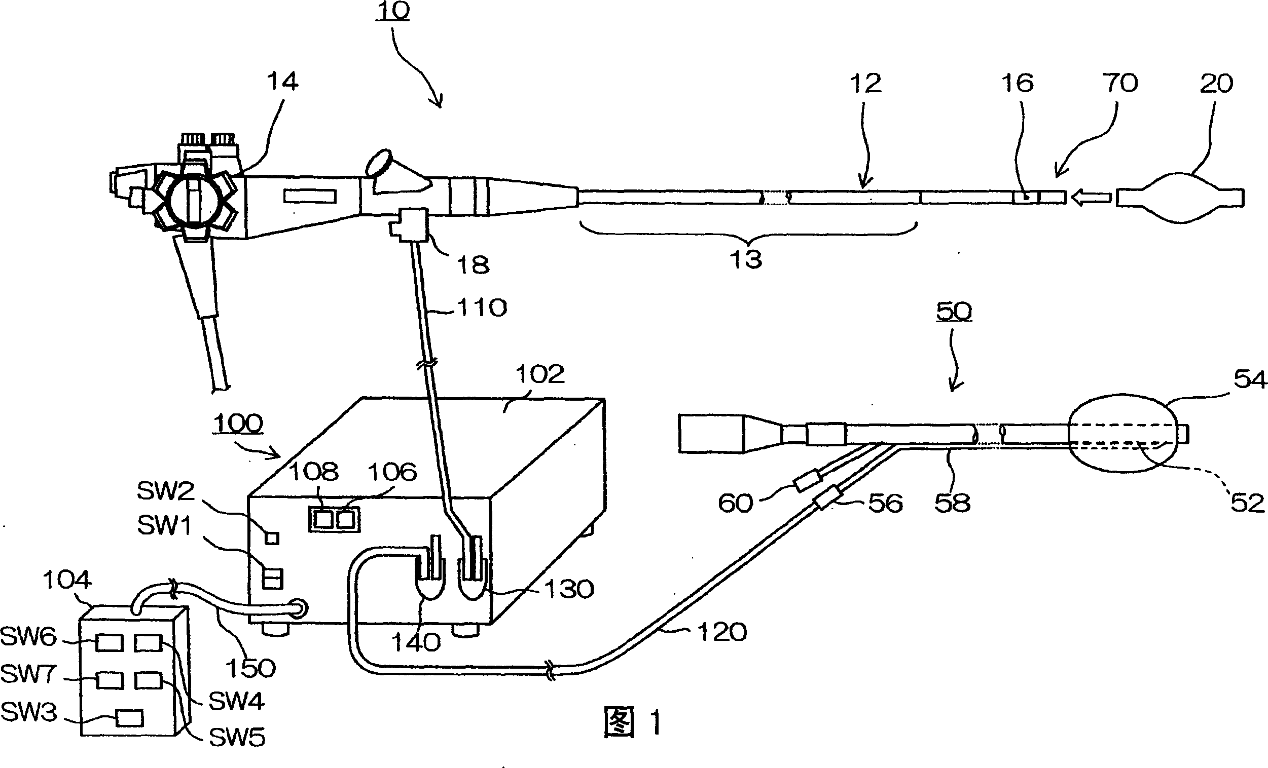
[0048] Fig. 1 is a system configuration diagram of an endoscope device composed of a balloon-type endoscope and a balloon control device according to the present invention.

[0049] The endoscope device shown in this figure has a double balloon endoscope composed of a balloon endoscope 10 and a cannula 50 and a balloon control device 100 .

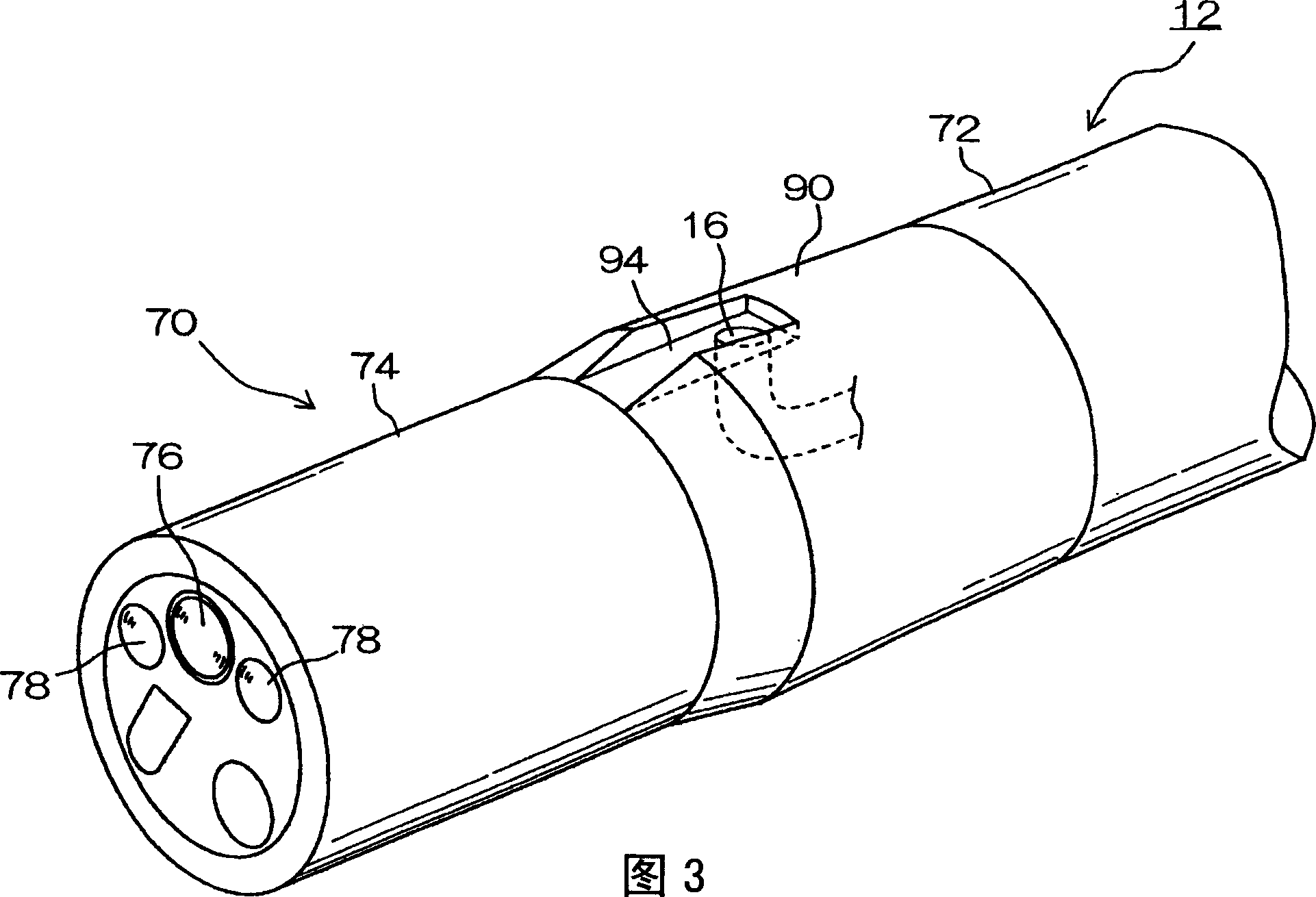
[0050] The balloon endoscope 10 is an electronic endoscope provided with an objective optical system 76 (refer to FIG. 3 ) and an imaging device (CCD) at the front end of the insertion portion 12. The observed image through the objective optical system 76 is imaged by the CCD, and Photoelectric conversion takes place here. The electrical signal representing the photoelectrically converted observation image is output to a processor (not shown) through the electric wires in the insertion part 12 and...


PUM


Abstract

A warning unit outputs an alert when a first abnormality detector and a second abnormality detector determine detachment or loosening of a tube (110) that can cause abnormal pressure in each balloon (20,54).

Description

technical field [0001] The present invention relates to an airbag type endoscope, in particular to an endoscope with a freely expandable airbag provided at the front end of the endoscope insertion part. In addition, the present invention relates to a balloon control device for a double-balloon endoscope capable of improving safety when using the double-balloon endoscope. Background technique [0002] A double-balloon endoscope is known as a device to replace the conventional small intestine endoscope. This double-balloon endoscope is composed of an endoscope with an air bag at the front end of the endoscope that can supply and suck air to the air bag, and a cannula as an insertion part that can be inserted into the endoscope. An airbag is provided and a cannula is configured to supply and suck air to and from the airbag (for example, Japanese Patent Application Laid-Open No. 51-11689 (page 2, FIG. 1 )). [0003] The air bag control device is connected to each air bag of th...

Claims


Application Information

Patent Timeline
IPC IPC(8): A61B1/015
CPCA61B1/015
Inventor 关口正
Owner FUJIFILM CORP
Learn More