Direct optical n-state phase shift keying

A phase-shifting, optical technology applied in the field of optical transmission systems

Inactive Publication Date: 2004-12-01
LUCENT TECH INC
View PDF0 Cites 5 Cited by
  • Summary
  • Abstract
  • Description
  • Claims
  • Application Information

AI Technical Summary

Problems solved by technology

In fact, an unsolved problem is that existing OPSK schemes can only perform phase...

Method used


Image

  • Direct optical n-state phase shift keying
  • Direct optical n-state phase shift keying
  • Direct optical n-state phase shift keying

Examples


Embodiment Construction

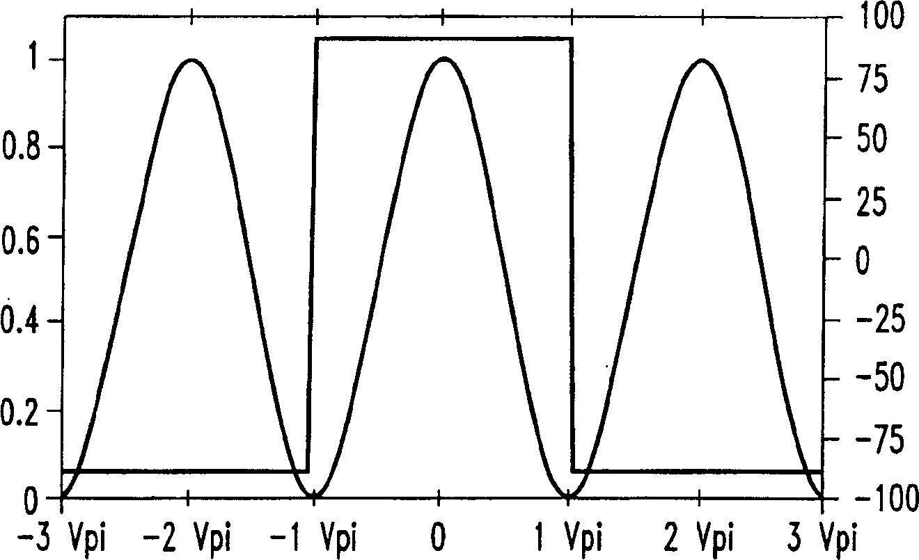
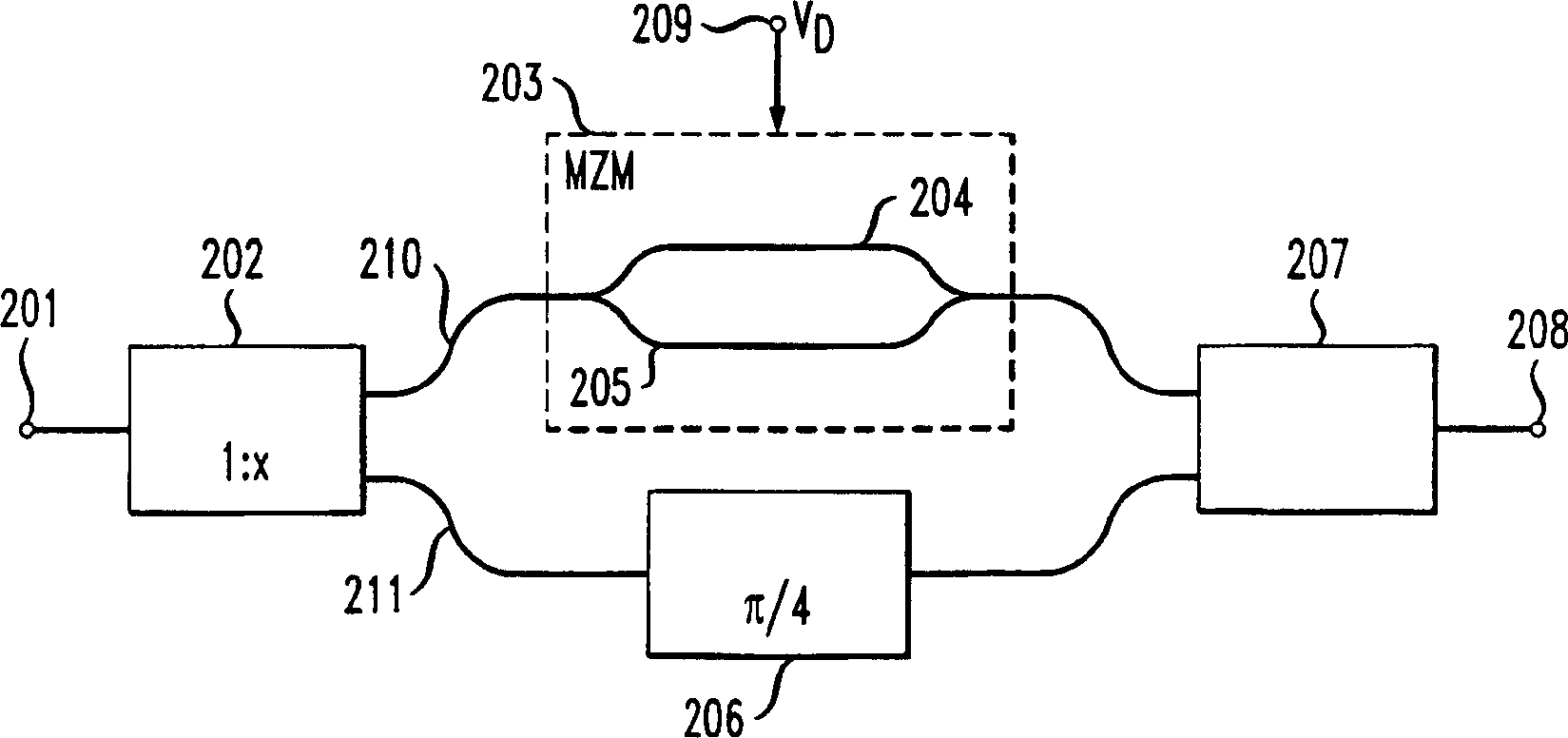
[0012] figure 1 is a graphical representation of the amplitude transfer function and phase response of an optical modulator such as a Mach-Zehnder optical modulator (MZM). Note that the phase response has a digital nature. If for example by entering 209 to figure 2 The average driving voltage (median driving voltage) V of the optical modulator of the shown MZM 203 D Chosen to be at the minimum of the amplitude transfer function, the phase of the supplied optical signal is modulated in a binary manner, thus having two phase states.

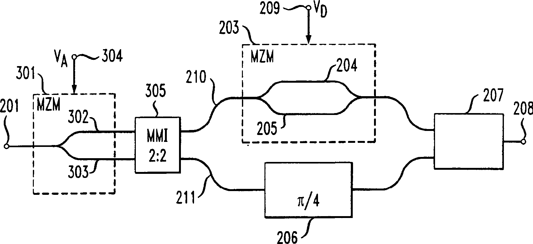
[0013] In order to transmit a higher bit to word count than the existing known schemes including those described above in the background section, the inventors propose a method such as figure 2 An encoder including an optical modulator is shown. This unique encoder is used to switch the phase of light in a binary fashion, but the two phase states can be chosen to differ by any desired angle. Therefore, if figure 2 As shown, coherent light...


PUM


Abstract

A unique optical encoder is employed that utilizes an optical phase modulator, in which an arbitrary phase shift can be realized. The phase modulator is driven by an electrical signal, where the voltage amplitude is proportional to a desired arbitrary phase shift. However, any amplitude noise or poor rise and fall times of the driving voltage translates directly into phase errors. These problems are eliminated by employing a digital phase switch. One encoder, in accordance with the invention, employs an optical phase modulator that can switch the optical phase in a binary manner, wherein the two phase states of the modulator can be chosen to differ by any desired arbitrary angle depending on the splitting ratio of the optical signal to be modulated.

Description

technical field [0001] The invention relates to an optical transmission system, in particular to phase shift keying of optical signals. Background technique [0002] Recently, there has been growing interest in alternative optical modulation formats for use in high bit rate optical communication systems. To this end, optical differential phase shift keying (ODPSK) is a promising candidate to increase system capacity, range, and spectral efficiency. However, until now, only Optical Differential Binary Phase Shift Keying (ODBPSK) and Optical Differential Quadrature Phase Shift Keying (ODQPSK) have successfully demonstrated higher bit rates, where Shift keying (ODBPSK) in the titled "2.5Tb / s (64×42.7Gb / s) transmission over 40×100km NZDSF using RZ-DPSK format and full Raman Gb / s) Transmission Over 40×100km NZDSF Using RZ-DPSKFormat and All-Raman-Amplified Spans)", by A.H.Gnauk et al., OFC 2002 is described in the article, while Optical Differential Quadrature Phase Shift Keyi...

Claims


Application Information

Patent Timeline
IPC IPC(8): G02F1/035G02F1/01H04B10/12H04B10/155H04L27/20
CPCH04L27/2096H04B10/505H04B10/5561H04B10/5053H04B10/5055H04B10/5051
Inventor 安德烈亚斯·利文
Owner LUCENT TECH INC
Why Eureka
Try Eureka