Motor with a brake

A technology of brakes and motors, applied in the field of motors, can solve problems such as overloading of the motor itself

Inactive Publication Date: 2004-12-01
TAMAGAWA SEIKI CO LTD
View PDF3 Cites 7 Cited by
  • Summary
  • Abstract
  • Description
  • Claims
  • Application Information

AI Technical Summary

Problems solved by technology

[0006] Therefore, when the motor is running for a long time, the same level of voltage as the initial excitation is continuously applied to the brake during operation, causing the brake to heat up, and the heat will also be conducted to the stator side, not only the brake, but also the motor itself will be overloaded
[0007] In addition, the brake drive voltage is determined by the brake used. Usually, this voltage is different from the voltage of the motor drive power supply. Therefore, it is necessary to prepare a brake drive power supply just to drive the brake.

Method used


Image

  • Motor with a brake
  • Motor with a brake
  • Motor with a brake

Examples


Embodiment Construction

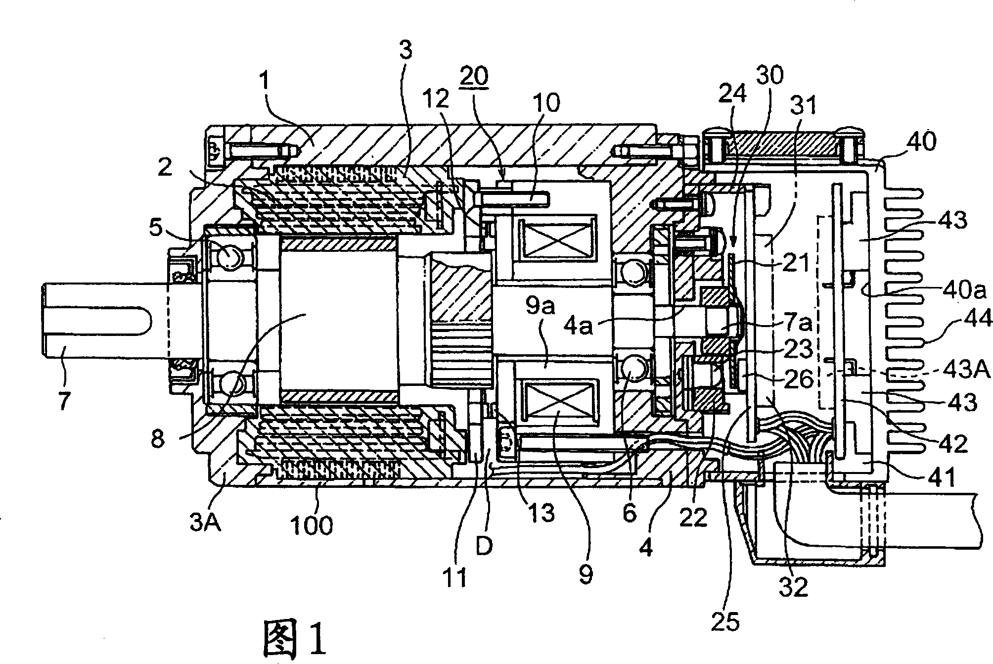
[0019] A preferred embodiment of the motor with brake according to the present invention will be described below with reference to the drawings.

[0020] Reference numeral 1 in FIG. 1 is a cylindrical casing with a stator 3 around which a stator coil 2 is wound. A front cover 3A and a rear cover 4 are installed at both ends of the cylindrical casing 1 .

[0021] Each bearing 5,6 is mounted on the front cover 3A and the rear cover 4, the rotating shaft 7 is freely rotatably mounted on each bearing 5,6, and the rotor 8 located inside the stator 3 is freely rotatably mounted on the rotating shaft 7, An electromagnetic driving part 9 with an excitation coil (not shown in the figure) is installed on the back cover 4 . The stator 3 , the rotor 8 and the encoder 30 constitute a servo motor unit 100 .

[0022] At the position on the side of the front cover 3A of the electromagnetic driving part 9 , the fixing plate 11 is fixedly assembled on the electromagnetic driving part 9 with bo...


PUM


Abstract

A motor with a brake in which, after an initial stage, a voltage applied to the brake is reduced to thereby restrain heat generation in the brake. In the motor with a brake, after signal drive, a voltage of a drive signal supplied to an electromagnetic drive portion of the brake is reduced, whereby heat generation in the brake during motor rotation is restrained, which makes it possible to increase a load to be applied to the motor.

Description

technical field [0001] The present invention relates to a motor with a brake, in particular to a new type of improvement. When the motor driving power is turned on and the initial excitation is performed for releasing the brake, the usual voltage is applied, and after the initial excitation, a lower voltage is passed. Excitation, thereby suppressing the coil heating of the electromagnetic drive part of the brake. Background technique [0002] In the motor with brake used in the past, when the motor is turned on, its electromagnetic drive part starts, and the brake is kept released through electromagnetic action. When the motor is turned off, the brake is closed by the action of the spring, so that the rotation of the rotor is stopped. state (for example, Patent Document 1). [0003] [Patent Document] JP-A-2000-50569 [0004] Since the conventional motor with a driver has the above structure, it has the following problems. [0005] In terms of structure, when the motor is ...

Claims


Application Information

Patent Timeline
Patent Type & Authority Applications(China)
IPC IPC(8): H02K7/102H02K11/04H02P3/04
CPCH02K7/1025H02K11/0073H02P3/04H02K11/33B21J7/22B21J13/02B21J13/085
Inventor 三浦啓正野田敏幸
Owner TAMAGAWA SEIKI CO LTD
Why Eureka
Try Eureka