Method and device for draining waste water in the inner bend of a beam blank casting machine

A technology of drainage device and slab guide device, which is applied in the field of draining waste water and devices from the inner arc of the I-beam billet casting machine, and can solve problems such as troubles and lack of space

A technology of drainage device and slab guide device, which is applied in the field of draining waste water and devices from the inner arc of the I-beam billet casting machine, and can solve problems such as troubles and lack of space

CN1551812AInactive Publication Date: 2004-12-01SMS DEMAG AG

Image

  • Method and device for draining waste water in the inner bend of a beam blank casting machine
  • Method and device for draining waste water in the inner bend of a beam blank casting machine
  • Method and device for draining waste water in the inner bend of a beam blank casting machine

Examples


Embodiment Construction

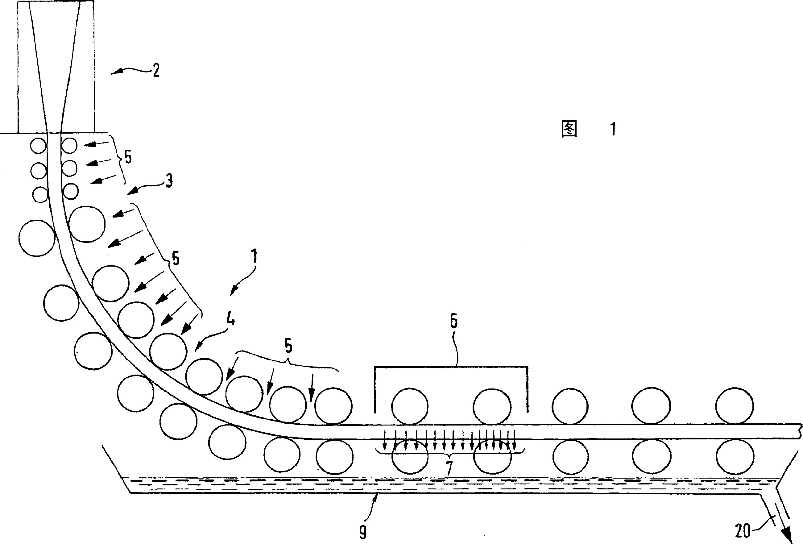
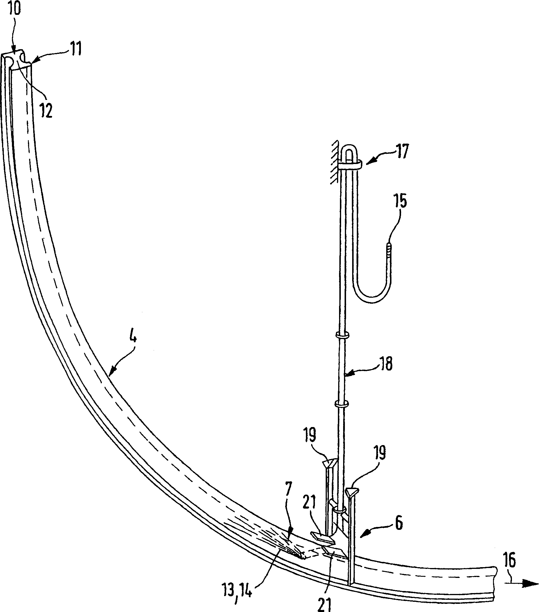
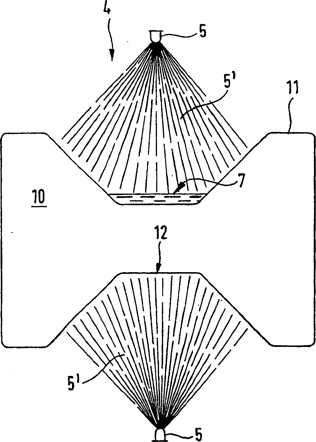
[0023] In the side view of Figure 1, an I-beam billet caster can be seen, which includes a crystallizer 2, a billet guide 3 with guide rollers and water spray nozzles 5, cooling water is sprayed on the billet guide Between the rollers of the device 3 to cool the cast I-beam billet such as the preform for I-beam rolling. The sprayed cooling water collects in the inner bend of the strand guide 3 and flows away in the inner bend 4 of the I-beam blank profile on the web between the profile flanges 11 in the direction of casting. The drainage accumulates along the nozzle row in the casting direction and hinders the heat transfer by means of water spray cooling on the one hand and causes water accumulation on the other hand which prevents the controlled cooling of the I-beam blank.

[0024] In order to overcome this problem, waste water is drained from the surface of the I-beam blank by means of a drainage device 6 in the region of the inner bend 4 of the I-beam blank. The waste wa...


PUM


Abstract

The invention relates to a method and a device for draining waste water (7) from the inner bend of the strand guide (3) of a beam blank casting machine. In order to drain said waste water from the beam blank in a targeted and controlled manner, a draining device (6) is arranged in the area of the strand guide (4) for the beam blank, said device being provided with jet nozzles (8). Under the effect of jets (13, 14) directed with high energy against the water flow direction, the waste water is lifted on the formation of a banking-up pressure by means of said draining device (6), directed at the lateral edges (11) of the inner bend (4) of the beam blank (10) and collected in a sintered groove (9), arranged thereunder.

Description

technical field [0001] The invention relates to a method and a device for draining waste water from the inner arc bend of a billet guide device of an I-beam billet caster. Background technique [0002] In the I-beam billet casting machine, the cast profile billet is completely solidified in the billet guide. Preliminary solidification is accomplished in the crystallizer by heat conduction from water-cooled copper plates. Further heat dissipation takes place in the strand guide by roller contact, heat dissipation by means of water spray nozzles and heat radiation. I-beam billet profiles are made in the casting radius of arc bending casting machines. According to this principle, waste water is collected on the inner arc of the I-beam blank profile. The waste water gradually accumulates between the nozzle rows in the casting direction and prevents the heat transfer by means of water spray cooling on the one hand and causes the water to collect in front of the torch cutting m...

Claims


Application Information

Patent Timeline
01 Dec 2004
Publication
CN1551812A
IPC
B22D11/124
CPC
B22D11/1248; B22D11/124
Inventors
D·勒特泽尔; H·布罗茨维