Damping arrangement for reducing combustion chamber pulsations in a gas turbine system

A technology of vibration reduction device and combustion chamber, which is applied in the direction of combustion chamber, continuous combustion chamber, combustion method, etc., and can solve the problems that the combustion chamber cannot be easily used

Inactive Publication Date: 2004-12-01
ANSALDO ENERGIA SWITZERLAND AG
View PDF1 Cites 30 Cited by
  • Summary
  • Abstract
  • Description
  • Claims
  • Application Information

AI Technical Summary

Problems solved by technology

[0008] All the above-mentioned measures for specifically reducing the combustion chamber pulsations occurring in the combustion chamber are individually adapted to the respective situation of the individual combustion chamber and cannot be easily used for other types of combustion chambers

Method used


Image

  • Damping arrangement for reducing combustion chamber pulsations in a gas turbine system
  • Damping arrangement for reducing combustion chamber pulsations in a gas turbine system
  • Damping arrangement for reducing combustion chamber pulsations in a gas turbine system

Examples


Embodiment Construction

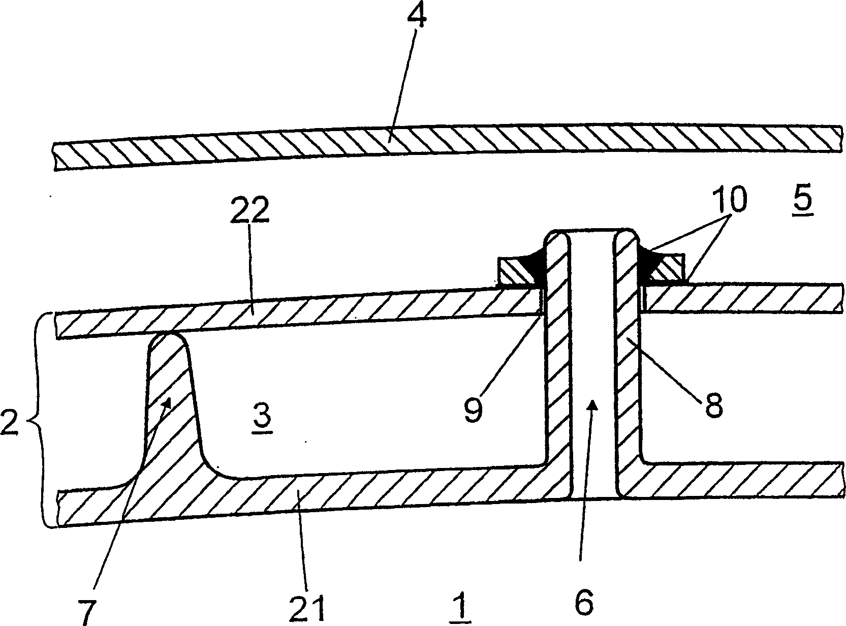
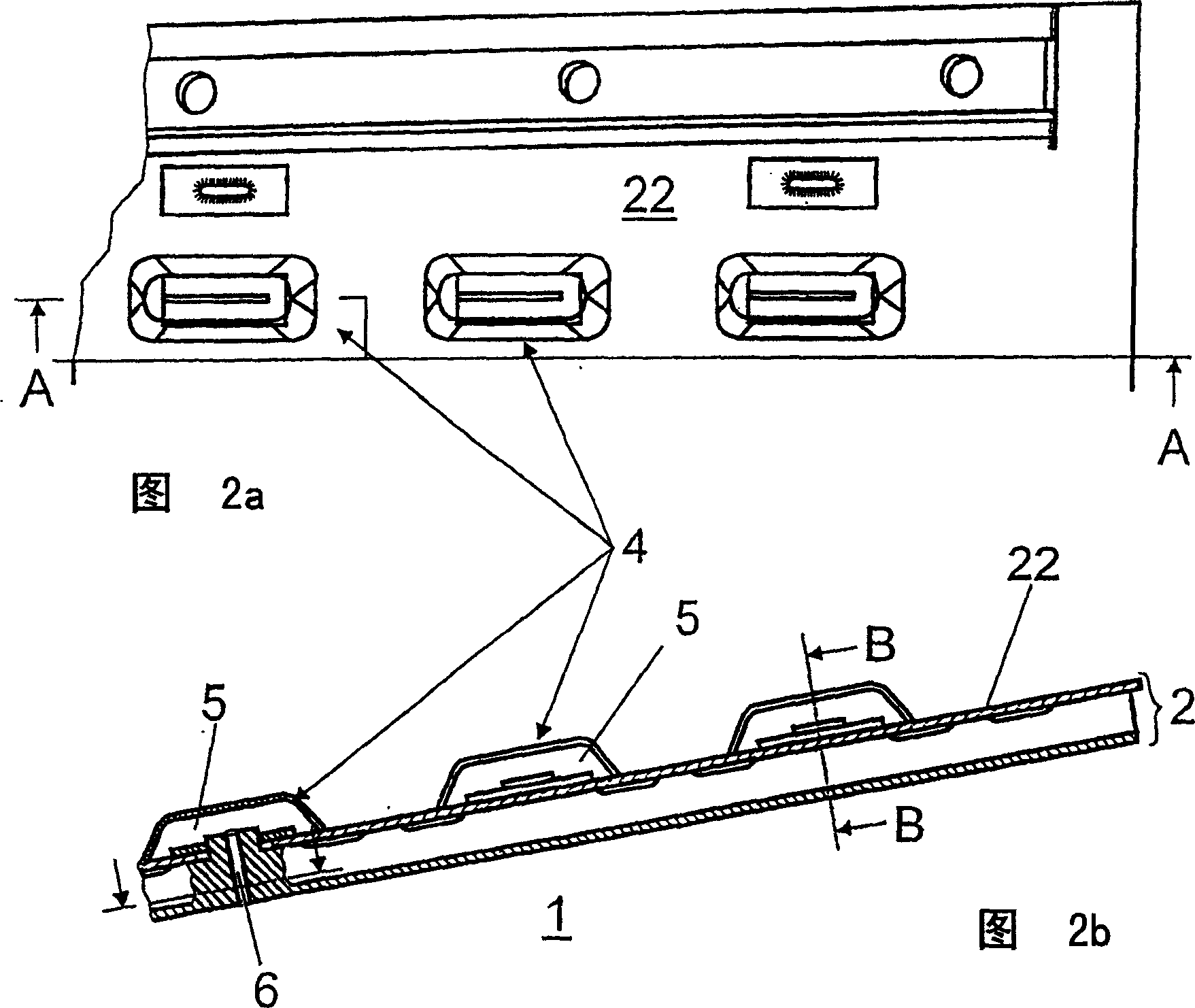
[0031] figure 1 A vibration damping device is shown in cross-section for reducing resonances in a combustion chamber 1 surrounded by a double-walled combustion chamber wall 2 with an outer wall part 22 and an inner wall part 21 encloses an intermediate chamber 3 in a gas-tight manner, into which cooling air can be fed in order to convectively cool the combustion chamber wall 2 and in particular the inner wall part 21 .

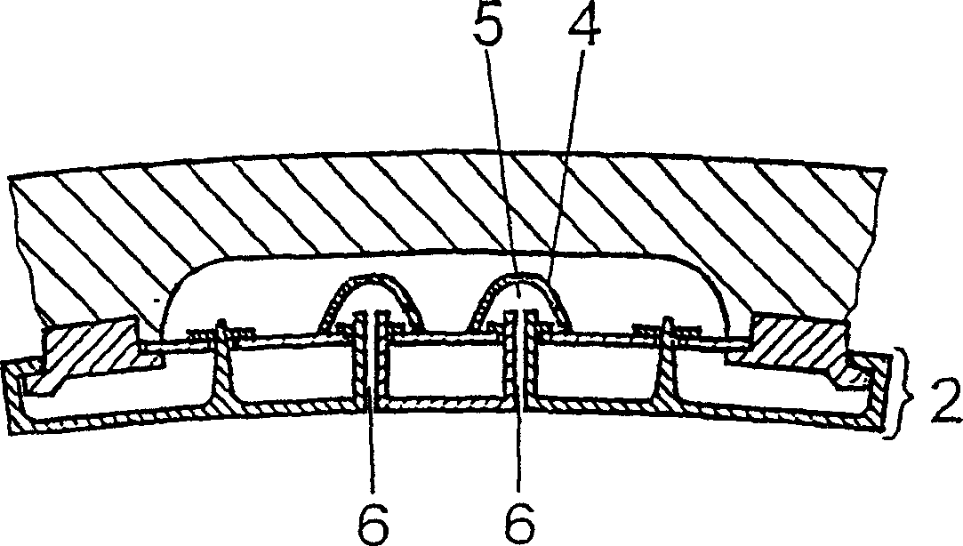
[0032] On the side of the outer wall part 22 facing away from the combustion chamber 1 there is a third wall part 4 which together with the outer wall part 22 encloses a gas-tight space, the so-called resonance space or absorption space 5 . Via a connecting line 6 in the form of a connecting tube, the absorption space 5 is directly connected to the combustion chamber 1 and at the same time an acoustically effective connection is created between the combustion chamber 1 and the absorption space 5 . In order to acoustically effectively damp the combustion chamb...


PUM


Abstract

A description is given of a damping arrangement for reducing resonant vibrations in a combustion chamber (1), with a combustion-chamber wall (2), which is of double-walled design and, with an outer wall-surface part (22) and an inner wall-surface part (21) facing the combustion chamber (1), gastightly encloses an intermediate space (3), into which cooling air can be fed for purposes of convective cooling of the combustion-chamber wall (2). The invention is distinguished by the fact that at least one third wall-surface part (4) is provided, which, with the outer wall-surface part (22), encloses a gastight volume (5), and that the gastight volume (5) is connected gastightly to the combustion chamber (1) by at least one connecting line (6).

Description

technical field [0001] The invention relates to a vibration damping device for reducing resonance in a combustion chamber having a double-walled combustion chamber wall which encloses an intermediate chamber gas-tight with an outer wall part and an inner wall part facing the combustion chamber, For convective cooling of the combustion chamber walls, cool air can be fed into the intermediate chamber. Background technique [0002] EP 0669500 ​​B1 discloses a combustion chamber having a chamber wall in the form of a double wall as described above. For cooling, the compressed combustion intake air flows through the closed intermediate chamber of the double-walled combustion chamber walls surrounding the combustion zone, the double-walled combustion chamber walls being cooled by convective cooling. Details regarding the construction of such a combustion chamber are known from the above-mentioned European patent document, the disclosure of which is hereby referred to. [0003] T...

Claims


Application Information

Patent Timeline
Patent Type & Authority Applications(China)
IPC IPC(8): F23R3/06F23M20/00F23R3/00F23R3/22
CPCF23R3/002F23R2900/00014F23M99/005F23M20/005
Inventor U·本茨J·赫拉特F·约斯
Owner ANSALDO ENERGIA SWITZERLAND AG
Why Eureka
Try Eureka