Discrete face mold device for plate material heat forming

A thermoforming, discrete technology, applied in the field of discrete profile molds, can solve the problems of complex hydraulic cylinder stroke control system, high cost, complex structure, etc., and achieve the effect of convenient operation and maintenance, low cost, and improved forming quality.

Inactive Publication Date: 2004-12-15
HUNAN UNIV
View PDF1 Cites 6 Cited by
  • Summary
  • Abstract
  • Description
  • Claims
  • Application Information

AI Technical Summary

Problems solved by technology

Because the device adopts the basic body of the hydraulic cylinder structure, it has the disadvantages of complex structure, complicated hydraulic cylinder stroke control system, high cost, and inconvenient maintenance.

Method used


Image

  • Discrete face mold device for plate material heat forming
  • Discrete face mold device for plate material heat forming
  • Discrete face mold device for plate material heat forming

Examples


Embodiment 1

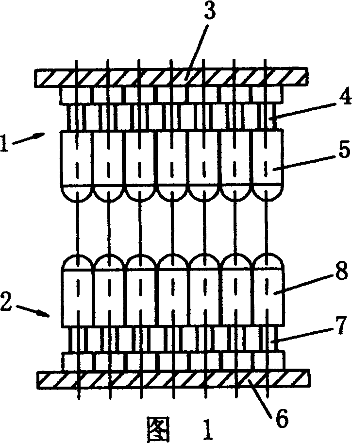
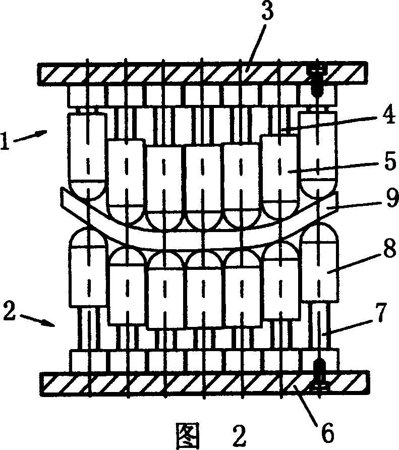
[0022] Example 1. See Figures 1 and 2. Comprising an upper die 1 and a lower die 2, the template 3 of the upper die 1 is provided with a number of closely arranged punches, and the punches are composed of a screw 4 connected to the template 3 and a head body 5 matched with the screw. The body 5 can be displaced along the axial direction of the screw 4; the template 6 of the lower die 2 is provided with a number of closely arranged punches, and the punches are composed of a screw 7 connected to the template 6 and a head body 8 matched with the screw , The head body 8 can be displaced axially along the screw rod 7; the punch on the upper die corresponds to the punch on the lower die. In this example, the corresponding punches on the upper and lower dies are on the same axis. The operation process is, firstly, through an additional adjustment device, adjust the height of the upper and lower die punch heads relative to the template to form the required forming surface, and drive...

Embodiment 2

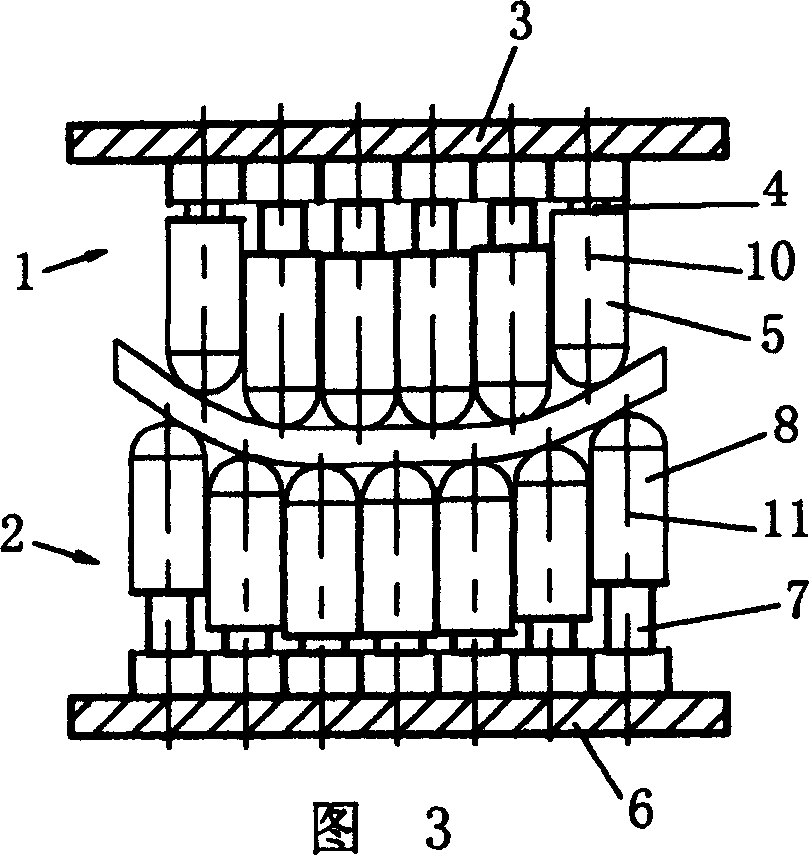
[0023] Example 2. See Figure 3. In this example, the punch on the upper die 1 and the corresponding punch on the lower die 2 are staggered and not on the same axis, that is, the axis 10 of the punch on the upper die 1 and the axis 11 of the corresponding punch on the lower die 2 Stagger each other. Others are with embodiment 1.

[0024] Figure 4 It is a top view schematic diagram of the corresponding punches on the same axis in the upper and lower dies in Fig. 1 and Fig. 2, the top view projections of the corresponding punches on the upper and lower dies overlap, and the center distance between each adjacent two punches in the upper and lower dies is D; Figure 5 and Figure 6 Respectively represent the form of the corresponding punch misalignment in the upper and lower dies, Figure 5 The solid line and dotted line in the figure represent the positions of the punches of the upper and lower dies respectively, indicating the relative displacement in the X and Y directions ...


PUM


Abstract

The discrete profile mold unit for heat plate formation includes upper mold, which has several closely arranged ram heads comprising screw connected to the template and matched head capable of shifting along the screw; lower mold, which has also several closely arranged ram heads comprising screw connected to the template and matched head capable of shifting along the screw. The ram heads in the upper mold and those in the lower mold are corresponding to each other and may be in the same or different axle. The present invention has the features of simple structure, low cost, convenient operation and maintenance, and adjustable ram head height.

Description

technical field [0001] The invention relates to a discrete surface mold for sheet material thermoforming, in particular to a discrete surface mold device suitable for blank workpiece forming. Background technique: [0002] On May 7, 2003, the utility model patent No. 02273508.9 "multi-point forming device for sheet metal" was announced. head), and are symmetrically on the same axis. The device adjusts the stroke of the punch through an adjustment device, and all the hydraulically driven basic bodies (punches) with different strokes are combined to form the required forming surface, and driven by the pressure equipment, the sheet is processed into a workpiece of corresponding shape. Because the device adopts the basic body of the hydraulic cylinder structure, it has the disadvantages of complex structure, complex hydraulic cylinder stroke control system, high cost, and inconvenient maintenance. Contents of the invention [0003] The object of the present invention is to p...

Claims


Application Information

Patent Timeline
Patent Type & Authority Applications(China)
IPC IPC(8): B21D13/02
Inventor 杨沿平莫旭辉钟志华
Owner HUNAN UNIV
Why Eureka
Try Eureka