Wear resistant casting ball automatic separator

A technology for automatic separation and wear-resistant cast balls, applied in the field of post-processing devices for wear-resistant cast balls, can solve the problems that restrict the large-scale, mechanized mass production of wear-resistant cast balls, harsh working environment, and high labor intensity. Achieve the effect of improving work efficiency, reducing production costs and reducing labor intensity

Active Publication Date: 2004-12-22
安徽省凤形新材料科技有限公司
View PDF0 Cites 9 Cited by
  • Summary
  • Abstract
  • Description
  • Claims
  • Application Information

AI Technical Summary

Problems solved by technology

Manual operation is not only inefficient, but also has a harsh working environment and high labor intensity. It has long been the bottleneck in the production of casting balls, which seriously restricts the large-scale and mechanized mass production of wear-resistant casting balls.

Method used


Image

  • Wear resistant casting ball automatic separator
  • Wear resistant casting ball automatic separator

Examples


Embodiment

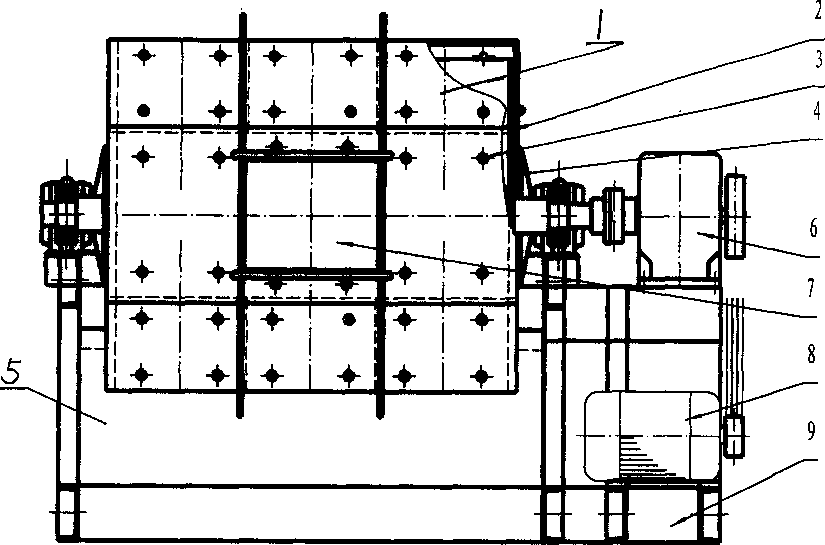
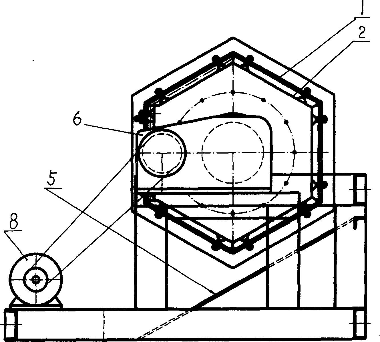
[0017] This embodiment includes a frame 9, a drum 1 and a transmission mechanism. The drum 1 is a hexagonal cylinder, and the drum 1 is fixedly installed on the frame 9 through the transmission shaft and the shaft seat at both ends. The material door 7 is installed on the drum 1, and the wear-resistant liner 2 is fixedly installed on the inner wall of the drum 1 in turn. , and fixed on the inner wall of drum 1 with evenly distributed fastening bolts 3, drive shafts are respectively installed at both axial ends of drum 1; The input shaft of the device 6 is connected with the motor 8 through a transmission belt, the output shaft of the reducer 6 is connected with the transmission shaft of the drum 1, and a discharge inclined guide plate 5 is installed below the drum 1 .

[0018] When in use, the one-piece casting ball with a pouring riser is added to the drum 1 from the material gate 7, and the material gate 7 is closed. Driven by the motor 8 and the reducer 6, the drum 1 rotate...


PUM


Abstract

An automatic separator for the antiwear cast balls is composed of machine frame, prismatic drum and drive unit. After the linked cast balls with sprute are loaded in its drum, the drum is driven by motor to rotate while the collesion and friction take place between said cast balls to separate them from each other and grind their surfaces.

Description

Technical field [0001] The invention relates to a post-processing device for wear-resistant cast balls, in particular to an automatic separator for wear-resistant cast balls. Background technique [0002] Wear-resistant casting balls are produced by casting sand molds, metal molds or lost foam. In order to improve production efficiency and process yield, manufacturers adopt a group casting method of multiple balls in one mold. At present, after the casting process is completed, the manufacturers use manual knocking to separate the casting balls from the casting balls, and the casting balls from the casting riser for the treatment of the conjoined wear-resistant casting balls after sand falling or demoulding. Manually grind and clean the sticky sand, spatter, bumps and fractures on the surface of the casting ball. Manual operation is not only inefficient, but also has a harsh working environment and high labor intensity. It has long been the bottleneck in the production of c...

Claims


Application Information

Patent Timeline
Patent Type & Authority Applications(China)
IPC IPC(8): B22D29/00B22D31/00
Inventor 陈宗明周利生储贵安
Owner 安徽省凤形新材料科技有限公司
Why Eureka
Try Eureka