Mobile satellite automatic tracing control device

An automatic tracking and moving satellite technology, applied in the field of satellite communication and positioning, can solve problems such as insufficient clarity, inability to automatically switch playback videos, and viewing interruptions.

An automatic tracking and moving satellite technology, applied in the field of satellite communication and positioning, can solve problems such as insufficient clarity, inability to automatically switch playback videos, and viewing interruptions.

CN1556419AInactive Publication Date: 2004-12-22青岛中嘉轨道交通技术有限公司

Image

  • Mobile satellite automatic tracing control device
  • Mobile satellite automatic tracing control device
  • Mobile satellite automatic tracing control device

Examples


Embodiment Construction

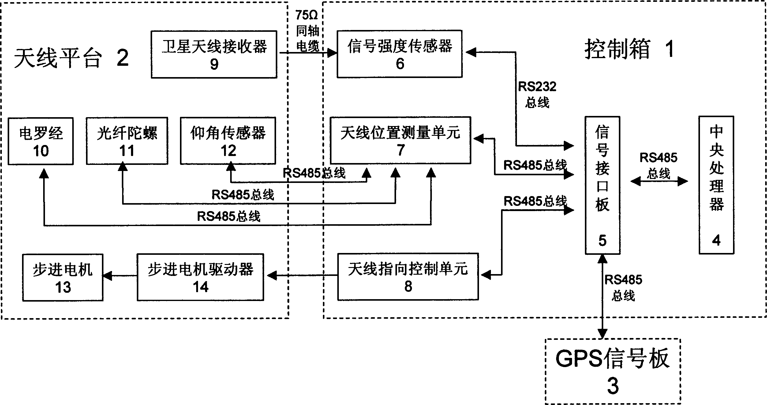
[0013] Such as figure 1 , The present invention is mainly composed of a control box 1 and an antenna platform 2. It is characterized in that the control box 1 includes a central processing unit 4, a signal interface board 5, a signal strength sensor 6, an antenna position measuring unit 7 and an antenna pointing control unit 8, and its They are connected by RS485 bus, and the antenna platform 2 includes a gyro compass 10, an optical fiber gyroscope 11, an elevation sensor 12, a satellite antenna receiver 9 and a stepping motor 13 connected to the antenna position measurement unit 7 respectively by the RS485 bus. Into the motor drive 14, and the drive 14 is controlled by the antenna pointing control unit 8 in the control box, and the satellite antenna receiver 9 is connected to the signal strength sensor 6 in the control box 1 via a 75Ω coaxial cable.

[0014] The signal strength sensor 6 adopts model ATP-01P and central processing unit 4 (model SBC4500). The signal interface boar...


PUM


Abstract

The control device includes control box, and antenna platform. The control box includes CPU, signal interface board, sensor of signal intensity, unit of measuring antenna position, and unit for controlling antenna pointing, which are connected to each other through RS 485 bus. The antenna platform includes following parts: electric gyrocompass connected to RS485 bus and unit of measuring antenna position, optic fiber gyroscope, elevation sensor, receiver of satellite antenna, which through coaxial line is connected to sensor of signal intensity in control box, and step motor controlled by the control box. A GPS signal receiving board is added in order to ensure uninterrupted received signal. Electric map software about way of this train is installed to CPU in order to get clear relevant images.

Description

Technical field [0001] The invention relates to satellite communication and positioning technology, in particular to a mobile satellite automatic tracking control device. Background technique [0002] New technologies such as satellite TV and high-fidelity stereo broadcasting have made modern trains a digital intelligent train integrating business office, leisure and entertainment, security monitoring, and information management services. However, existing satellite tracking control devices still accept TV. The program is not clear enough, and when the train passes through blind areas such as tunnels, the video cannot be automatically switched to play, resulting in interruption of viewing. Summary of the invention [0003] The purpose of the present invention is to overcome the shortcomings of the prior art and provide a mobile satellite automatic tracking control device. [0004] The technical scheme of the present invention is: composed of a control box and an antenna platform...

Claims


Application Information

Patent Timeline
22 Dec 2004
Publication
CN1556419A
IPC
G01C21/20; G01S1/08; H04B7/14
Inventors
梁保山; 姜德志