Ultra high energy spark plug

A spark plug, ultra-high technology, applied in the field of spark plugs, can solve problems such as unsuitable, unable to achieve high voltage and high current at the same time, and limited discharge energy

Inactive Publication Date: 2004-12-22
TIANJIN UNIV
View PDF0 Cites 33 Cited by
  • Summary
  • Abstract
  • Description
  • Claims
  • Application Information

AI Technical Summary

Problems solved by technology

Therefore, it is impossible to achieve high voltage and high current at the same time, so the discharge power is limited
Due to the limited discharge energy, this spark plug cannot ignite the lean mixture in the engine cylinder, so it is not suitable for lean-burn engine applications

Method used


Image

  • Ultra high energy spark plug
  • Ultra high energy spark plug
  • Ultra high energy spark plug

Examples


Embodiment Construction

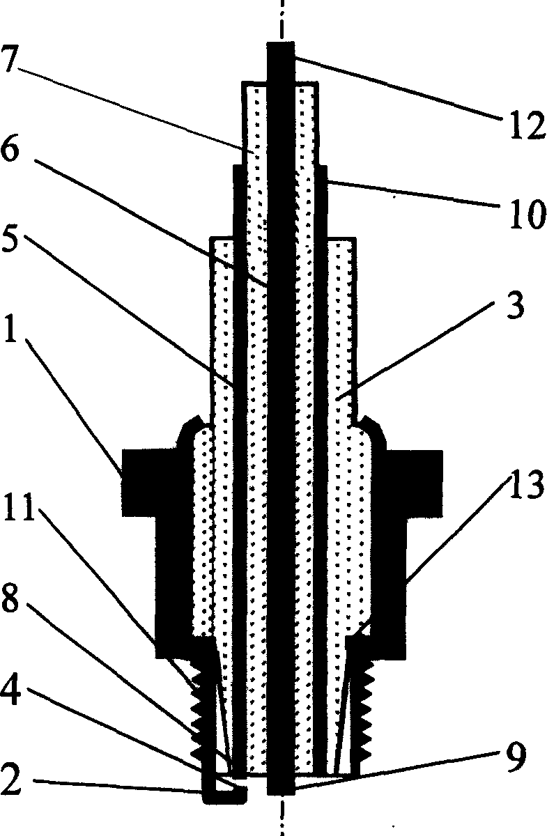
[0010] as attached figure 1 As shown, the ultra-high-energy spark plug is composed of a shell 1, a side electrode 2, and an insulator 3, wherein the shell 1 and the side electrode 2 are integrated by welding. The insulator 3 is located inside the housing 1 , the lower part of the housing 1 has a mounting thread 11 , and the lower end of the side electrode 2 is the discharge terminal 4 of the side electrode. Inside the shell 1, there is a high-voltage electrode 5 and a high-energy electrode 6, and the high-voltage electrode 5, high-energy electrode 6, and the shell 1 are separated by an insulator 3. The lower end of the high voltage electrode 5 is the high voltage electrode discharge end 8 , and the upper end is the high voltage electrode input end 10 . The lower end of the high-energy electrode 6 is the high-energy electrode discharge end 9 , and the upper end is the high-energy electrode input end 12 . The distance between the high-voltage electrode discharge end 8 and the ...


PUM


Abstract

The invention relates to a superenergy spark plug applied to a combustion engine firing system. It is mainly made up of shell, side electrode, and insulator. The lower part of the side electrode is a discharging end. A high voltage electrode and a superenergy electrode are arranged in the shell, the two electrodes and the shell are separated with insulators. The distribution method of the superenergy electrode and the high voltage electrode may adopt several methods. The discharging step is divided into discharging of high voltage electrode and the discharging of superenergy electrode. The superenergy discharging spark is generated between the superenergy electrode and the side electrode through the gas plasma generated by the high voltage discharging, the single time discharging energy can reach above 20 joules. The invention can enlarge the combustion limit of mixed gas in the engine cylinder, thus achieves the aim reducing the discharging of engine and upgrading the economy of the engine.

Description

technical field [0001] The invention relates to a spark plug technology used in an ignition system of an internal combustion engine. Background technique [0002] The spark plug used in the current internal combustion engine ignition system is composed of a shell, a center electrode and a side electrode, wherein the shell and the side electrode are made into one by welding, an insulator is between the shell and the center electrode, and the center electrode and the side electrode The lower ends are the respective electrode discharge ends. When working, a pulsed high-voltage electrical signal (voltage above 10,000 volts) is input to the center electrode, so that the gas between the center electrode and the discharge end of the side electrode is broken down to generate a spark discharge. The disadvantage of this ignition technology is that the spark discharge energy can only reach within 100 millijoules. The reason for limiting the discharge e...

Claims


Application Information

Patent Timeline
Patent Type & Authority Applications(China)
IPC IPC(8): H01T13/20
Inventor 汪洋余本雄朱涛董明哲蒋宁涛
Owner TIANJIN UNIV
Why Eureka
Try Eureka