
Minicomputer intelligent lockset system

A microcomputer and intelligent technology, which is applied in the field of electronic technology and information, can solve the problems of easy breakdown, less password digits, intelligent restrictions, etc., and achieve the effect of stable performance and preventing misoperation

Inactive Publication Date: 2005-01-05
江苏中兴建设有限公司
View PDF1 Cites 2 Cited by
  • Summary
  • Abstract
  • Description
  • Claims
  • Application Information

AI Technical Summary

Problems solved by technology

[0002] Nowadays, general-purpose mechanical locks generally have shortcomings such as easy duplication and weak insurance performance. Some people can even open most mechanical locks without a key; Lost, the product is not universal, and it is inconvenient to use
There are also some disadvantages in the existing combination locks: simple on-off combination locks, few password digits, inconvenient modification, and weak confidentiality
The password lock of the digital gate circuit is inconvenient to modify, cannot be automatically detected, and lacks intelligence
The CUP controls the computer board code lock, and it cannot be connected to the personal computer. The intelligence is limited, and it is difficult to meet the requirements of home intelligence.
The electric locks commonly used in the former combination lock system do not have the function of automatic security, it is easy to forget to secure after closing the door, and the anti-prying ability is poor
The driving circuit of many electric locks uses a triode circuit, which works under the condition of inductive load, and is easy to break down and cause failure
There are also some electric locks that are driven by AC contactors, and arcing and sparking often occur on the contacts. Over time, contact oxidation, burning, burning, etc. will occur. The reliability is poor, the failure rate is high, and the system stability is poor.

Method used


Image

  • Minicomputer intelligent lockset system
  • Minicomputer intelligent lockset system
  • Minicomputer intelligent lockset system

Examples


Embodiment Construction

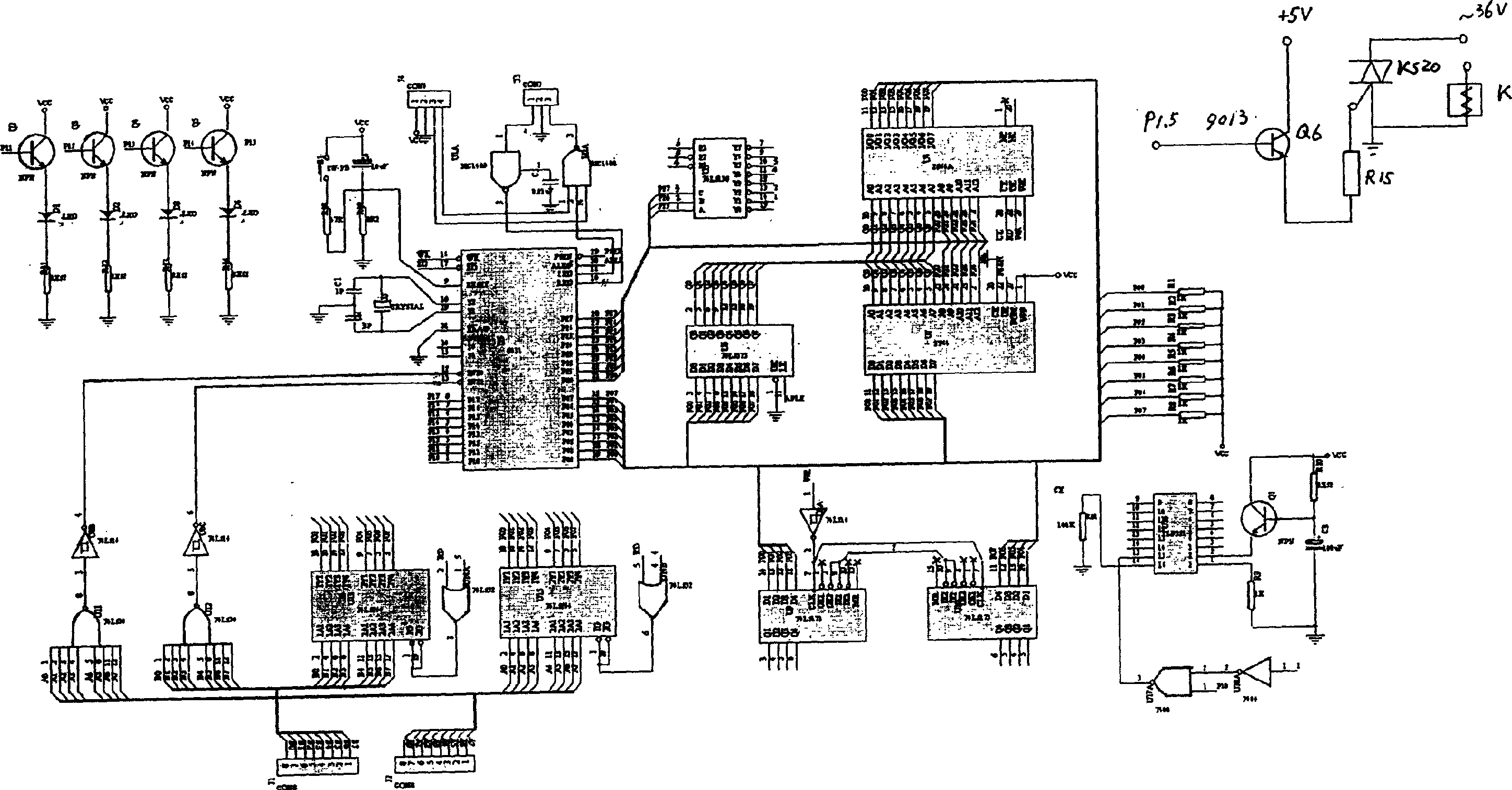
[0015] Manifold part: U1 is MC1489, U2 is MC1488, U3 is 74LS138, U4 is 2864A, U5 is 8031, U6 is 74LS373, U7 is 2764, U8 is 74LS14, U9 and U10 are 74LS173, U11 and U12 are 74LS30, U13, U15 is 74LS244, U14 is 74LS32, U16 is TLP521, U17 is 7400, U18 is 7404.

[0016] Transistor part: Q1, Q2, Q3, Q4, Q5 are 9014 or 9013, Q6 is 9013.

[0017] Resistance part: R1, R2, R3, R4, R5, R6, R7, R8 are 1KΩ, R9 is 100Ω, R10 is 10KΩ, R11, R12, R13, R14 are 500Ω, R15 is 10Ω, 0.5W, R18 is 47KΩ, R19 is 8KΩ, R81 is 100KΩ.

[0018] Capacitor part: C1 and C2 are 3PF, C3 is 100Uf, C4 is 10Uf, C5 is 0.01Uf, and other filtering and power purification use 47uF electrolytic capacitors and larger ceramic capacitors.

[0019] The electromagnet in the electric lock should use a 36V AC coil, and the current should be less than 2A.

[0020] The thyristor adopts KS20 / 500.

[0021] in working:

[0022] 1. Remotely modify the password online with the PC

[0023] After the system is powered on, it has been...


PUM


Abstract

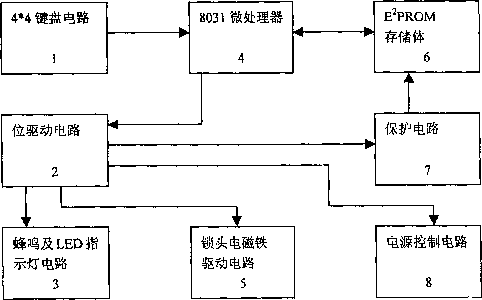
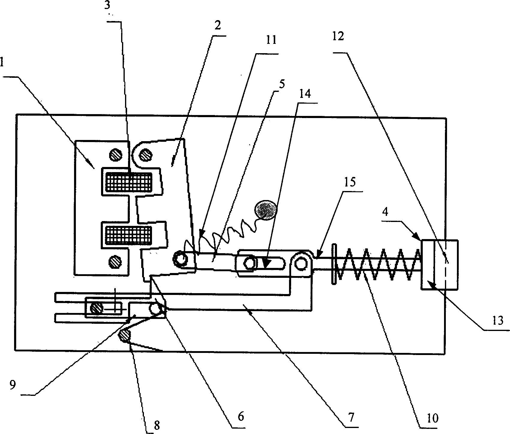
The invention is microcomputer intelligent lock system, which mainly made up of keyboard circuit, bit driving circuit, microprocessor, and lock head electromagnetic driving circuit, memory, protecting circuit, power control circuit. The keyboard circuit, bit driving circuit, and the memory are connected to the microprocessor directly; the buzz instructing light circuit, lock head electromagnetic driving circuit, power control circuit, and the protecting circuit are connected to the bit driving circuit; the protecting circuit controls the read and write of the memory; the microprocessor is connected with a PC to change the cipher code; the direct current electric signal uses the thyristor to control the alternate current power of the electric lock; a returning hook device is arranged in the electric lock for ensuring the safety when closing the door. The lock uses electron switch, has no arc or spark; the inputted cipher code may reach to 16 bits, it can change the cipher code online.

Description

technical field [0001] The invention relates to an electronic control device, belonging to the fields of electronic technology and information technology. Background technique [0002] Nowadays, general-purpose mechanical locks generally have shortcomings such as easy duplication and weak insurance performance. Some people can even open most mechanical locks without a key; Lost, the product is not universal, and it is inconvenient to use. Existing multiple coded locks also have some disadvantages: the simple switch type coded lock has few code digits, inconvenient modification, and weak security. The combination lock of the digital gate circuit is inconvenient to modify, cannot be automatically detected, and lacks intelligence. The CUP controls the combination lock of the computer board and cannot be connected with the personal computer, so the intelligence is limited, and it is difficult to meet the requirements of family intelligence. The electric locks commonly used in...

Claims


Application Information

Patent Timeline
Patent Type & Authority Applications(China)
IPC IPC(8): E05B47/06E05B49/00
Inventor 焦悦
Owner 江苏中兴建设有限公司
Learn More