

Electrothernal tube and its forming method
A molding method and technology of electric heating tubes, applied in the direction of heating element shape, etc., can solve problems such as expansion and contraction damage, affecting assembly, and difficult to control the external dimensions of electrical connection ends
- Summary
- Abstract
- Description
- Claims
- Application Information
AI Technical Summary
Problems solved by technology
Method used
Image

Examples
Embodiment Construction
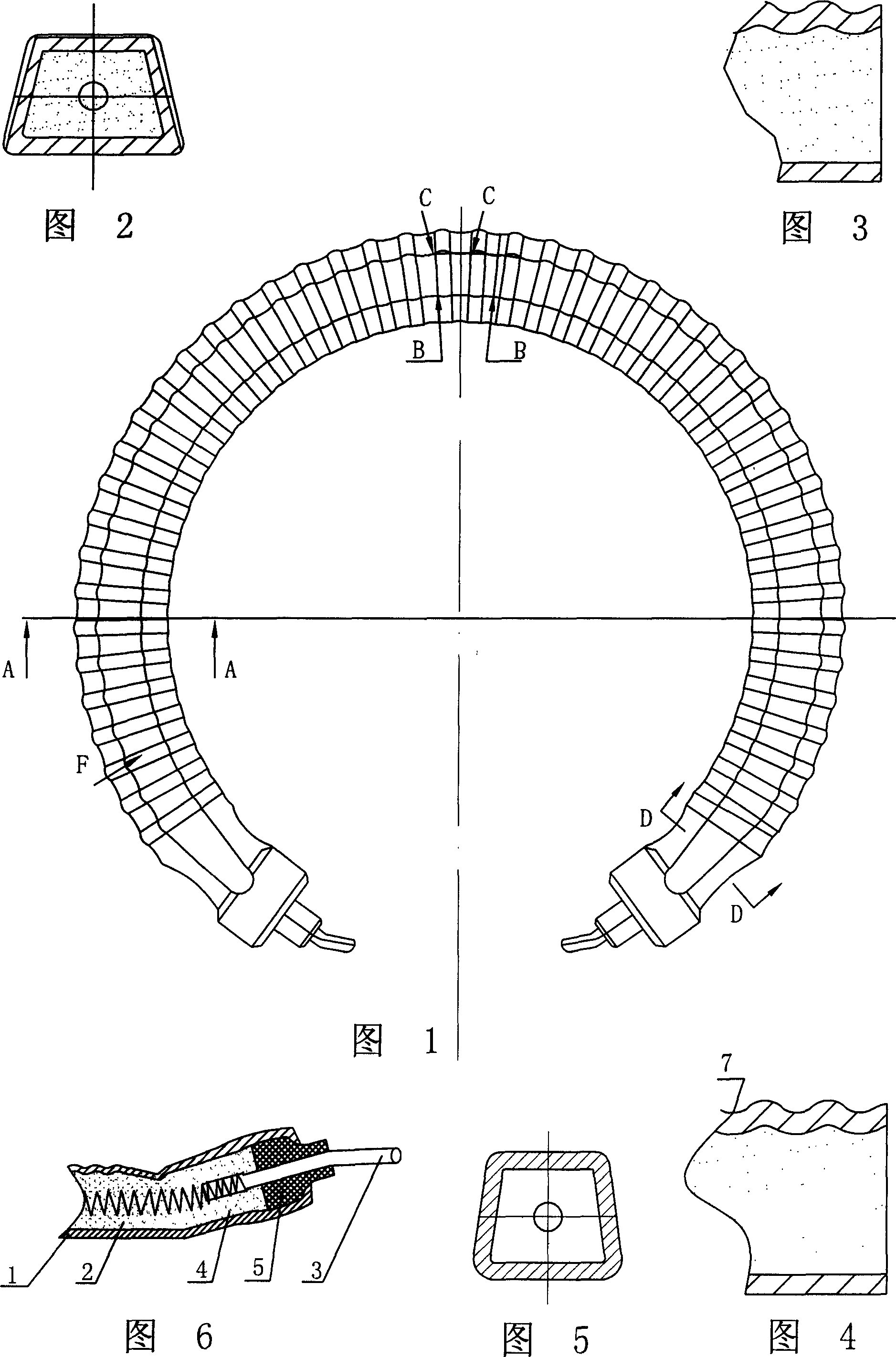
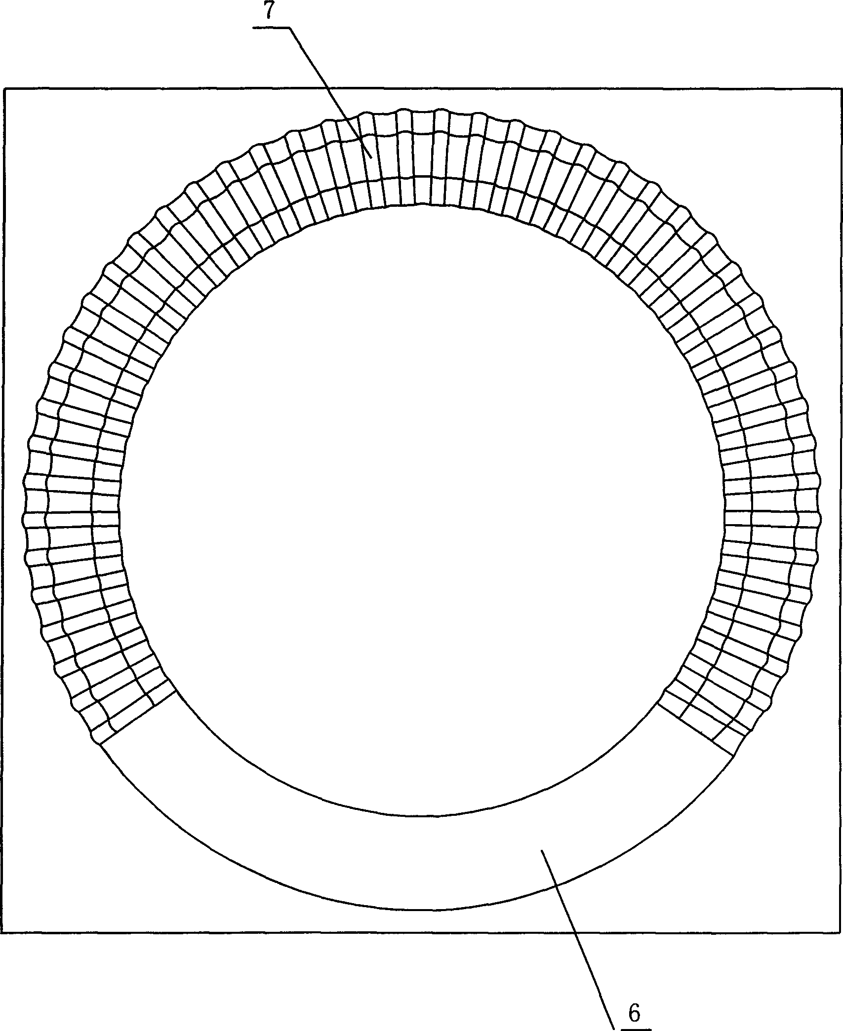
[0016] Below in conjunction with the accompanying drawings, the specific embodiment of the forming method of the electric heating pipe of the present invention is described in further detail:
[0017] The electric heating tube of the present invention includes a metal tube 1 , an insulating powder 2 , a resistance wire 4 , an insulating member 5 , and a metal rod 3 . The metal tube 1 is an aluminum tube, the insulating powder 2 is magnesium oxide powder, the insulating member 5 is a ceramic column, and the metal rod 3 is a steel lead column.
[0018] As shown in Figs. 1-6, the electric heating pipe is formed by bending a metal pipe 1 with a circular cross-section into a C-shape, and then punching the surface to have a concave-convex structure and at least one surface is a plane structure. The advantage is that the circular metal tube 1 is easy to bend, and the distance between the resistance wire 4 and the wall of the metal tube 1 is uniform. The metal rod 3 is set in the ins...
PUM
 Abstract
Description
Claims
Application Information