Reducing color segregation in HID lamps

A discharge lamp and signal technology, applied in the use of gas discharge lamps, output power conversion devices, high-efficiency power electronic conversion, etc., can solve problems such as high color temperature and low efficiency

Inactive Publication Date: 2005-01-05
KONINKLIJKE PHILIPS ELECTRONICS NV
View PDF2 Cites 2 Cited by
  • Summary
  • Abstract
  • Description
  • Claims
  • Application Information

AI Technical Summary

Problems solved by technology

This phenomenon results in high color temperature and low efficiency

Method used


Image

  • Reducing color segregation in HID lamps
  • Reducing color segregation in HID lamps
  • Reducing color segregation in HID lamps

Examples


Embodiment Construction

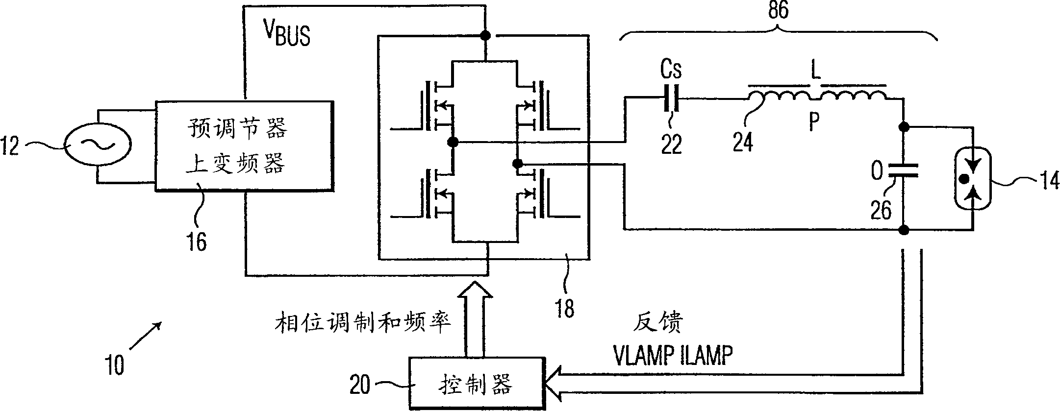
[0034] figure 1 An electronic ballast circuit 10 according to one embodiment of the present invention is shown. The main power supply 12 provides an AC current signal to the high and low voltage power bus, V BUS is ultimately used to drive the lamp 14 . The ballast circuit 10 includes a pre-regulator and upconverter 16 configured to receive a rectified signal of the mains power signal and shape the ballast supply current (which may also be referred to as the mains current) for power factor correction. Advantageously, the pre-regulator and up-converter 16 comprises a boost converter (not shown), the operation of which is well known in the art.

[0035] The ballast bridge unit 18 is configured to receive the signals provided by the pre-regulator and up-converter 16 . The ballast bridge unit 18 has the function of a commutator, that is, the polarity of the voltage signal supplied to the lamp 14 is changed through the filter circuit 86 . The ballast bridge unit 18 includes fou...


PUM


Abstract

A system and method for driving a gas discharge lamp. In one embodiment, the system comprises a bridge circuit for generating a pulse voltage signal wherein the bridge circuit has an operational frequency, a power input for receiving power from a power source, and a control signal input for receiving a control signal that effects sweeping of the operational frequency and generation of the pulse voltage signal. The system further includes a controller for controlling the bridge circuit, the controller comprising circuitry for (i) generating a signal comprising a frequency swept signal that is amplitude modulated by a fixed frequency signal wherein the signal generated by the controller is inputted into the control signal input of the bridge circuit, and (ii) periodically sweeping the operational frequency of the bridge circuit. The system further includes a filter circuit for filtering the pulse voltage signal.

Description

[0001] This application is a continuation-in-part of US Application No. 09 / 684196, filed October 6, 2000, the entire contents of which are incorporated herein by reference. technical field [0002] This invention relates to systems for driving gas discharge lamps, and more particularly to systems using pulse width modulation for reducing color segregation in high intensity discharge lamps. Background technique [0003] High intensity discharge (HID) lamps have become more and more popular due to their many advantages such as high efficiency and high light intensity. These HID lamps are driven by high-frequency electronic ballasts or low-frequency electronic ballasts. High-frequency electronic ballasts can generate driving current signals in the range of about 20KHz, and low-frequency electronic ballasts have driving current signals in the range of 100Hz. [0004] However, the main obstacle to using high frequency electronic ballasts for HID lamps is the possible acoustic res...

Claims


Application Information

Patent Timeline
Patent Type & Authority Applications(China)
IPC IPC(8): H05B41/24H05B41/292H05B41/36H05B41/392
CPCY02B20/208H05B41/3928Y02B20/202H05B41/2928H02M7/4815Y02B20/00Y02B70/10H05B41/26H05B41/24H05B41/292
Inventor D·A·卡马克
Owner KONINKLIJKE PHILIPS ELECTRONICS NV
Why Eureka
Try Eureka