Controllable LED stage lights

A technology of light-emitting diodes and stage lights, which is applied to semiconductor devices of light-emitting elements, light sources, lampshades, etc., can solve the problems of slow color switching, limited time for changing colors, limited rotation speed of the turntable, complex mechanical transmission structure, etc. The effect of short color time, high utilization rate of lighting energy and simple mechanical structure

Inactive Publication Date: 2005-01-12
SHANGHAI INST OF OPTICS & FINE MECHANICS CHINESE ACAD OF SCI
View PDF1 Cites 21 Cited by
  • Summary
  • Abstract
  • Description
  • Claims
  • Application Information

AI Technical Summary

Problems solved by technology

[0003] 1) The mechanical transmission structure is complex and takes up a lot of space;
[0004] 2) The time to change the color is limited by the rotation speed of the turntable, and the color switching is too slow;
[0005] 3) Adjustable soft light is achieved by setting a soft light mirror on the turntable, and the effect is poor;
[0006] 4) The stage light consumes a lot of power;
[0008] 1) The lighting direction adjustment of the stage lights is not flexible;
[0009] 2) The light energy utilization rate of light-emitting diodes is not high;
[0010] 3) The image projection function of stage lights is poor;
[0011] 4) The realization of multi-color is achieved by controlling the light-emitting diodes on and off, which affects the life of the light-emitting diodes

Method used


Image

  • Controllable LED stage lights
  • Controllable LED stage lights
  • Controllable LED stage lights

Examples


Embodiment 1

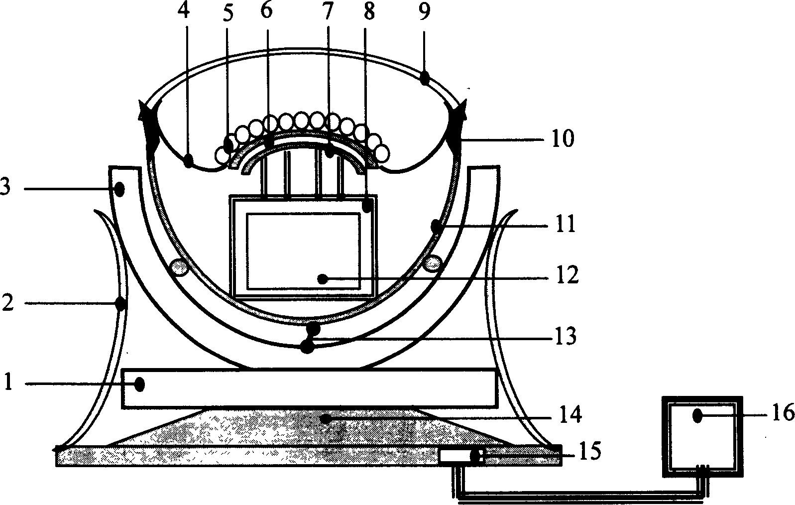
[0040] figure 1 It is a schematic cross-sectional view of the structure of Embodiment 1 of the controllable light-emitting diode stage light of the present invention. It can be seen from the figure that the controllable light-emitting diode stage light of the present invention includes two parts: the lamp head and the control support. The lamp head is coaxial from the outside to the inside The ground is the front end lampshade 9, the LED array 5, the diode flexible support plate 6, the printed circuit board 7, the tiny electronic box 8, the control circuit board 12, the lamp holder protective cover 11, and the reflection condenser 4 and the fixed Connect ring 10. The control circuit board 12 is placed in the tiny electronic box 8 . The diode flexible support plate 6 has through holes for fixing the light emitting diodes, the light emitting diodes can be plugged on the diode flexible support plate 6, and the diode pins are connected to the circuit on the control circuit board ...

Embodiment 2

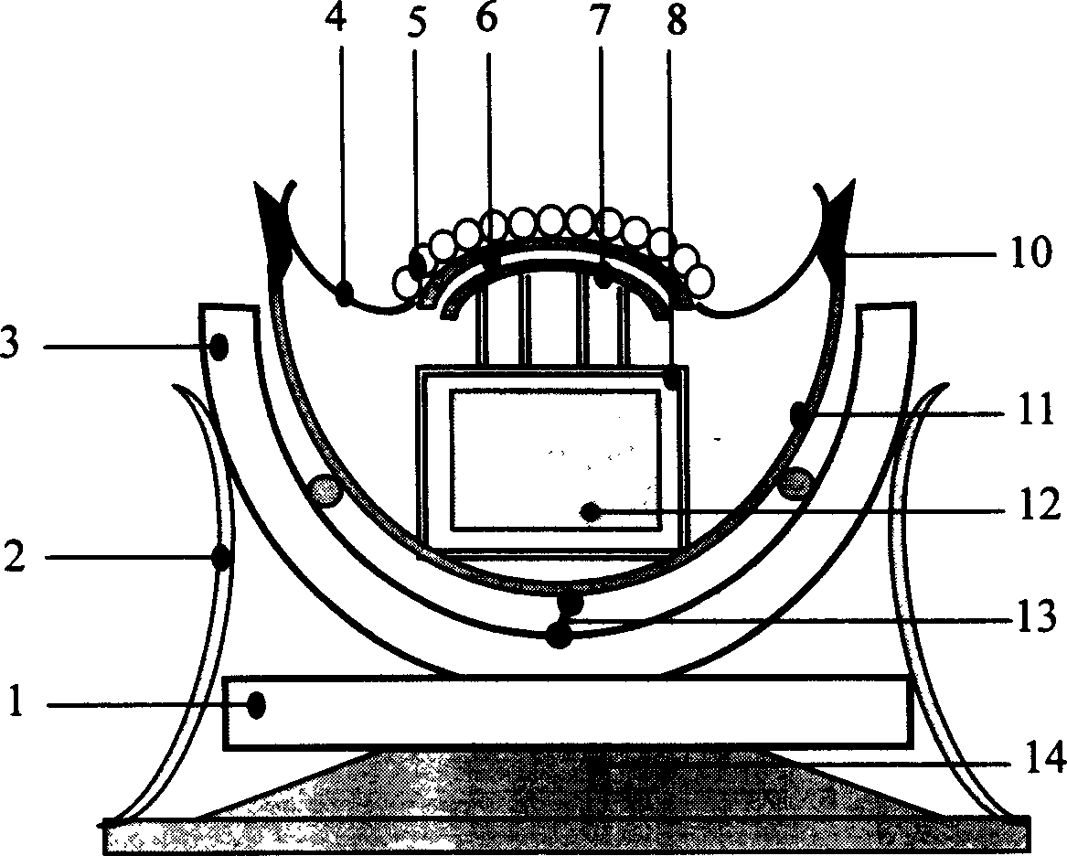
[0047] A controllable light-emitting diode stage light in this embodiment further integrates the above-mentioned embodiments and is applied to outdoor lighting decoration, including two parts: an integrated lamp head and a control support. Such as image 3shown. The integrated lamp head part includes a light emitting diode array 5; includes a diode flexible support plate 6 for fixing and supporting the light emitting diode array 5; includes a printed circuit board 7 corresponding to the diode flexible support plate 6; Surface 4 and lamp head protective cover 11; including control circuit board 12 and controller 16 in tiny electronic box 8; including fixed connection ring 10. The control support part includes a controllable one-dimensional circular arc mover 3 and a controllable rotator 1, one end of the movable connecting rod 13 is movably connected with the lamp head protective cover 11, and the other end is connected with the moving parts of the one-dimensional circular arc...


PUM


Abstract

The controllable stage LED lighting device has controllre and control circuit to control the lighting strength and color of LEDs in different position so as to realize the regulation of stage lighting in strength, color and softness. The controller controls the direction regulating part comprising rotating unit and circular moving unit to realize the free regulation of lighting direction and automatic stage lighting control. The reflecting lamp shade raises the light energy utilization of the LEDs, and the front lamp shade is used in projecting pattern. The built-in controller makes the stage lighting device integrated, small and portable for field use.

Description

technical field [0001] The invention relates to a stage lamp, in particular to a controllable light-emitting diode stage lamp, which is mainly suitable for stage, entertainment place and indoor and outdoor lighting and decoration. Background technique [0002] There are basically two implementations of today's stage lights: one is a stage light with different colors and different soft light effects composed of lamp tubes and filters, and the filter on the optical path is changed by a mechanical rotating mechanism; the other is It is a stage light based on light-emitting diodes (utility model patent, multi-color zoomable light-emitting diode stage light, ZL patent number: 97214709.8), which controls the micro-zones of different colors of light-emitting diodes in the light-emitting diode array to achieve multi-color. Although the two solutions in the prior art have their own advantages, there are still some shortcomings. The disadvantages of the first option are: [0003] 1)...

Claims


Application Information

Patent Timeline
Patent Type & Authority Applications(China)
IPC IPC(8): F21S10/00F21V3/02F21V21/14F21Y115/10
Inventor 高秀敏徐文东周飞张锋杨金涛
Owner SHANGHAI INST OF OPTICS & FINE MECHANICS CHINESE ACAD OF SCI
Why Eureka
Try Eureka