Position phase-difference enlarger of combined interferometer

A technology of amplifying device and phase difference, which is applied in measurement devices, optical devices, instruments, etc., can solve the problems of limited magnification and high requirements for optical path adjustment

Inactive Publication Date: 2005-01-12
SHANGHAI INST OF OPTICS & FINE MECHANICS CHINESE ACAD OF SCI
View PDF0 Cites 7 Cited by
  • Summary
  • Abstract
  • Description
  • Claims
  • Application Information

AI Technical Summary

Problems solved by technology

At present, the main method is to use the high-order diffraction term of the nonlinear hologram to realize phase difference amplification, but its magnification is limited by the diffraction order; using a certa...

Method used


Image

  • Position phase-difference enlarger of combined interferometer
  • Position phase-difference enlarger of combined interferometer
  • Position phase-difference enlarger of combined interferometer

Examples


Embodiment Construction

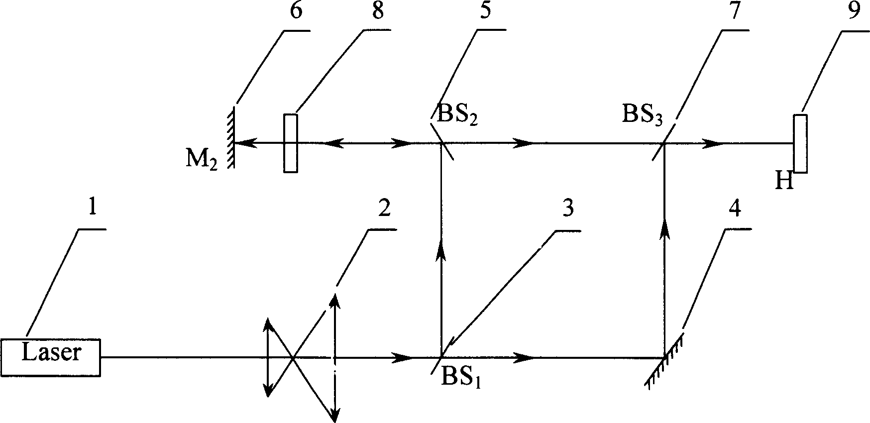
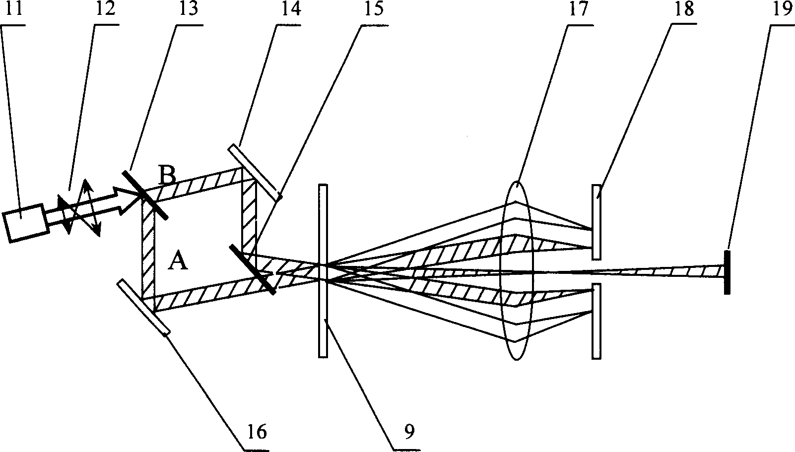
[0046] see first figure 1 , figure 2 , it can be seen from the figure that the combined interferometer phase difference amplification device of the present invention includes two parts: a hologram forming device and a hologram reconstruction device:

[0047] The composition of described hologram forming device is: a helium-neon laser light source 1 and on this laser light source 1 laser output light path, be provided with beam expander telescope 2 and be 45 ° first beam splitter 3 with light path successively, in the first The reflected optical path of beam splitter 3 is provided with the second beam splitter 5 that is 45 °, and the reflected optical path of this second beam splitter 5 is provided with sample 8 and the second total reflection mirror 6 successively, in the second total reflection mirror 6 The forward direction of the reflected light beam is the sample 8, the second beam splitter 5, the third beam splitter 7 and the dry plate 9 at an angle of 135° to the optic...


PUM


Abstract

The disclosed equipment combines M-Z interferometer with T-G interferometer. Phase factor is magnified in 2(M+N) times in the invention. Comparing with prior art, the phase factor is doubled in the invention.

Description

Technical field: [0001] The invention relates to holographic phase difference amplification, in particular to a combined interferometer phase difference amplification device. Background technique: [0002] The holographic method for phase difference amplification can be used to accurately measure the quality of optical components, and can also be used to detect the phase change of the system caused by stress, pressure, etc. At present, the main method is to use the high-order diffraction term of the nonlinear hologram to realize phase difference amplification, but its magnification is limited by the diffraction order; using a certain coherence length of the illumination source, let the beam pass through the phase object multiple times to achieve phase difference amplification , but the adjustment requirements for the optical path are very high. Invention content: [0003] The technical problem to be solved by the present invention is to overcome the defects of the above-m...

Claims


Application Information

Patent Timeline
IPC IPC(8): G01B9/021G01B11/00G03H1/00
Inventor 陈建文高鸿奕朱化凤李儒新徐至展
Owner SHANGHAI INST OF OPTICS & FINE MECHANICS CHINESE ACAD OF SCI
Why Eureka
Try Eureka