VLSI realizing method of synchronous flowing arithmetic coder

An arithmetic encoder and implementation method technology, applied in the field of VLSI design, can solve the problems of not giving key circuits and CX table operations, not considering the optimization of the critical path of the arithmetic encoder pipeline, key circuit implementation and auxiliary steps, etc.

Inactive Publication Date: 2005-01-12
XI AN JIAOTONG UNIV
View PDF0 Cites 9 Cited by
  • Summary
  • Abstract
  • Description
  • Claims
  • Application Information

AI Technical Summary

Problems solved by technology

In "High speed implementation of JBIG Arithmetic coder" [1], M.Tarui proposed to use the pipeline to realize the arithmetic coding in JBIG, mainly through the improved Qe table to realize the update of the CX table. Keng-Khai in "A high throughput context -based adaptive arithmetic codec for JPEG2000” [2], while using the pipeline design, a bitstuffing process is proposed, and an outline structure design is given, K-F.Chen in “Analysis and architecture design of EBCOT in JPEG2000” [3] in At the same time as the outline structure design is given, it is proposed to divide the register C (hereinafter referred to as CREG) into 16 bits and 12 bits to reduce the critical path, but [1] is mainly aimed at the arithmetic encoder in JBIG, and the Qe table is modified to increase the memory, which is 4 steps Pipeline; [1][2][3] did not give the operation of the key circuit and CX table, and did not consider the optimization of the key path, key circuit implementation and auxiliary steps that must be considered for the complete implementation of the arithmetic coder pipeline

Method used


Image

  • VLSI realizing method of synchronous flowing arithmetic coder
  • VLSI realizing method of synchronous flowing arithmetic coder
  • VLSI realizing method of synchronous flowing arithmetic coder

Examples


Embodiment Construction

[0022] The present invention will be further described in detail below in conjunction with the accompanying drawings and the embodiments given by the inventor.

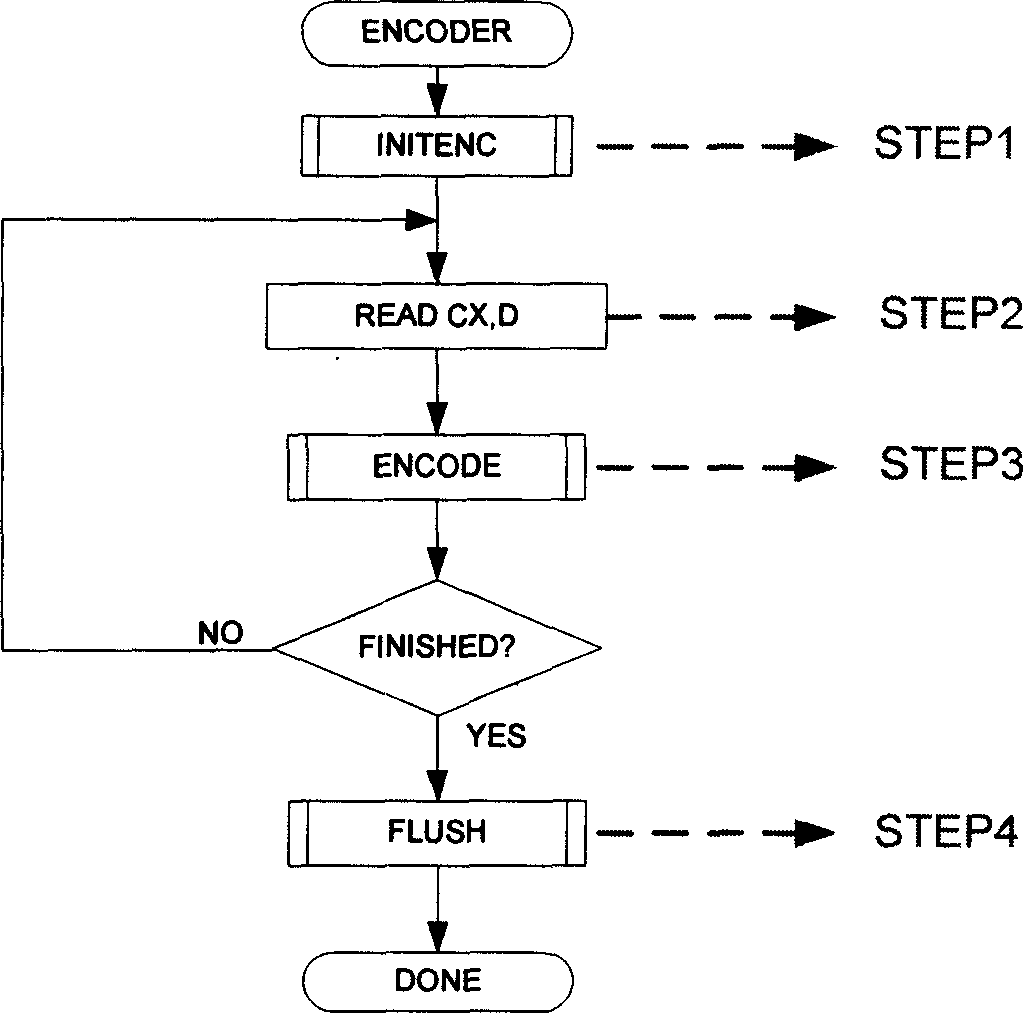
[0023] A brief description of the process of the arithmetic encoder of JPEG2000:

[0024] step1: INITENC: the register called when initializing the encoding

[0025] step2: read in CX (context label1), D (0, 1)

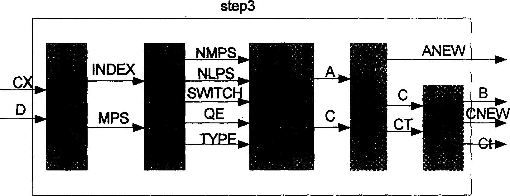
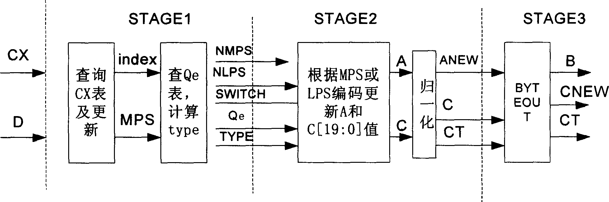
[0026] step3: Encoding (ENCODE), RENORME needs to be introduced in the encoding.

[0027] CODEMPS Conditions:

[0028] ((D=0)&(MPS(CX)=0))||((D=1)&(MPS(CX)=1))

[0029] CODELPS conditions:

[0030] ((D=1)&(MpS(CX)=0))||((D=0)&(MPS(CX)=1))

[0031] step4: FLUSH, output the data in REGC and cache after encoding.

[0032] The process of step3 is as follows figure 2 As shown, when A=0X8000H, and when CT is 0, the coded stream is output to the buffer (byteout). It can be seen that a complete encoding process requires at least 4 clock cycles. If normalization is required...


PUM


Abstract

The invention discloses a method for designing structure and key circuit of synchronous pipelining arithmetic coder suitable to hardware of image compression and video processing. For instance, JPEG2000 chip is capable of coding N pieces of input within N+3 timing cycle based on context-sensitive self-adapting arithmetic coder. Thus, following change is taken: flow of arithmetic coder in JPEG2000 protocol is converted to pipeline structure in three steps and assistant steps; putting forward optimizing algorithm in second and third steps in pipeline, index selection logic of Qe table under continuous CX input etc. Optimized result meets requirement of 200M timing clock under .25 micro techniques.

Description

technical field [0001] The invention belongs to the technical field of VLSI design. It specifically relates to a VLSI implementation method of a synchronous pipeline arithmetic coder in the hardware implementation of image compression or video processing. Background technique [0002] The context-based adaptive arithmetic coder is used in the JPEG2000 standard, but the process provided in the standard is more suitable for serial implementation of software. In the development of JPEG2000 chips, if the process in the standard is used, the state machine is used to To implement an arithmetic encoder, at least 4 clocks are required to encode an input, plus byteout, 6-7 clocks are required. In "High speed implementation of JBIG Arithmetic coder" [1], M.Tarui proposed to use the pipeline to realize the arithmetic coding in JBIG, mainly through the improved Qe table to realize the update of the CX table. Keng-Khai in "A high throughput context -based adaptive arithmetic codec for ...

Claims


Application Information

Patent Timeline
Patent Type & Authority Applications(China)
IPC IPC(8): G06T1/00G06T9/00
Inventor 梅魁志郑南宁刘跃虎姚霁王勇
Owner XI AN JIAOTONG UNIV
Why Eureka
Try Eureka