Fiber collecting device for ring spinning frame

A spinning frame and fiber technology, which is applied in the field of fiber strand gathering and compacting device in the drafting system of ring spinning frame, which can solve problems such as accidental drafting of fiber strands, failure of compacting force provided by the gathering top roller, unreliable power transmission, etc.

Inactive Publication Date: 2005-01-19
DONGTAI TEXTILE MASCH CO LTD
View PDF0 Cites 12 Cited by
  • Summary
  • Abstract
  • Description
  • Claims
  • Application Information

AI Technical Summary

Problems solved by technology

On the one hand, there are two stages of friction transmission in this device, and the power transmission is unreliable; on the other hand, because the accumulation top roller cannot provide enough pressing force, otherwise it will not only complicate the structure, but also may form a new Spinning triangular area, so it cannot provide enough frictio

Method used


Image

  • Fiber collecting device for ring spinning frame
  • Fiber collecting device for ring spinning frame
  • Fiber collecting device for ring spinning frame

Examples


Embodiment Construction

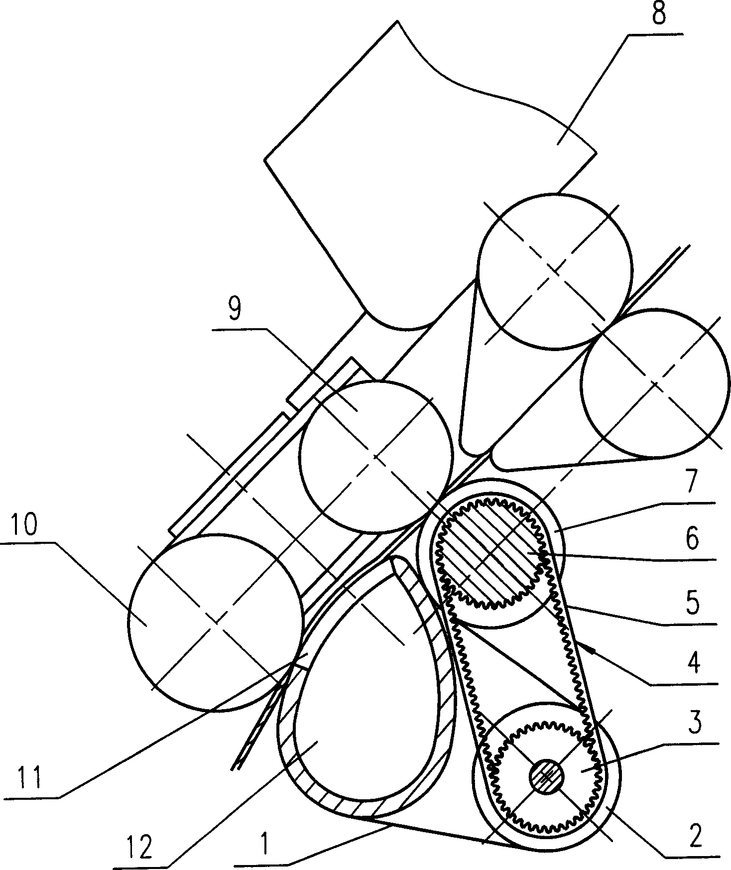
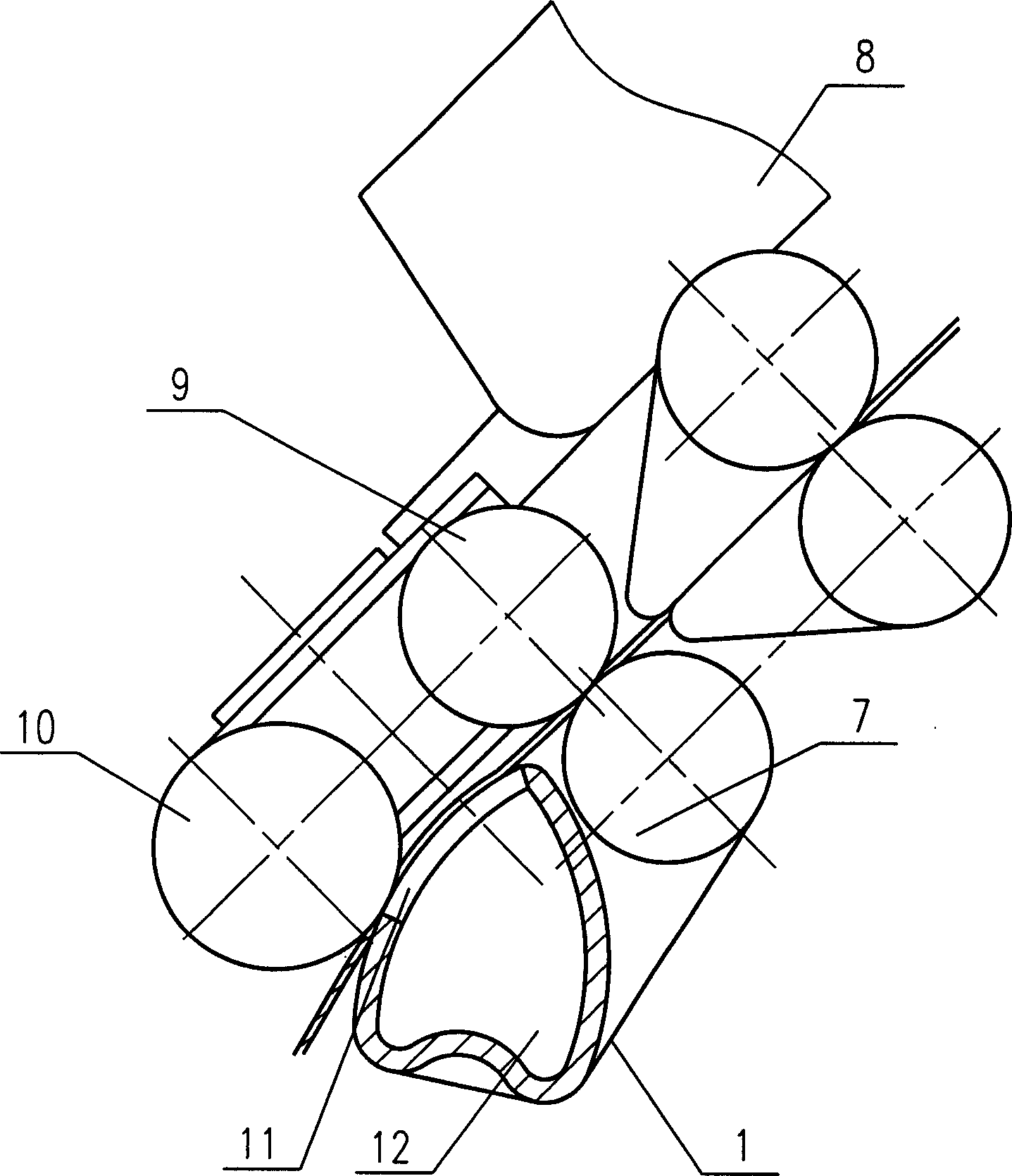
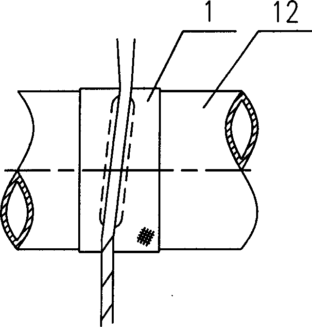
[0016] figure 1 The shown structure only shows a schematic view of the end area of ​​the fiber drafting and gathering device arranged on each spinning position of a ring spinning frame. In the figure, the front top roller 9 and the accumulation top roller 10 are rotatably supported on the same support frame, and the front top roller 9 is mounted on the front end of the cradle 8 under pressure; There is a suction pipe 12 below the air suction pipe 12, and there are several suction grooves 11 on the suction pipe 12. The suction pipe 12 is connected with a negative pressure air source, and the conveyor belt 1 is set on the suction pipe 12 and the middle driving roller 2. The position of each suction slot 11 on the suction pipe 12 and the conveyor belt 1 on it corresponds to the fiber bundle of each spindle position; the front roller 7 and the intermediate drive roller 2 are transmitted through the belt drive Power; the front side of the front roller 7 is in contact with the conv...


PUM


Abstract

The invention discloses a fiber nesting device for ring spinning frame, which comprises a front roller, a front leather roller, a nesting leather roller, and an indraft tube arranged under the nesting leather roller. An indraft groove is arranged on the top of said indraft tube, which slideably muffcouples a conveying belt, said conveying belt is driven by the front roller via belt driving unit or directly muffcoupled on the front roller. The fiber nesting device not only effectively avoids the spinning triangular space, but also ensures matching of the nipper jaws output speed with the conveying belt linear speed, so the resultant yarn quality is further improved.

Description

Technical field [0001] The invention relates to a ring spinning frame, in particular to a fiber strand gathering and compacting device in the drafting system of the ring spinning frame. Background technique [0002] In the traditional spinning system, when the fiber strands pass through the drafting system of the ring spinning machine in the rear area and the front area of ​​the drafting system and reach the nip of the front roller, the fiber strands are output to the twisting point where they are twisted into spun yarns. There is a spinning triangular area without twisting in between, because the fibers are basically out of control in this triangular area, especially the fibers at the edge of the triangular area cannot be gathered and twisted into the fiber bundle, and it is easy to leave and protrude from this area and become flying flowers And hairiness, together with the fact that the tension of the fibers in each part of the triangular area is not consistent, which ulti...

Claims


Application Information

Patent Timeline
IPC IPC(8): D01H5/72
Inventor 朱鹏王皓王平
Owner DONGTAI TEXTILE MASCH CO LTD
Why Eureka
Try Eureka