Contamination detecting method for LCD cell panel and sampling tool therefor

A contamination detection and liquid crystal technology, applied in measurement devices, preparation of test samples, instruments, etc., can solve problems such as inability to clearly know the composition or concentration of liquid crystals, and difficulty in sampling

Inactive Publication Date: 2005-01-19
AU OPTRONICS CORP
View PDF0 Cites 6 Cited by
  • Summary
  • Abstract
  • Description
  • Claims
  • Application Information

AI Technical Summary

Problems solved by technology

However, the composition or concentration of contamination sources of liquid crystals cannot be clearly known
Especially, because of the difficulty of sampl

Method used


Image

  • Contamination detecting method for LCD cell panel and sampling tool therefor
  • Contamination detecting method for LCD cell panel and sampling tool therefor
  • Contamination detecting method for LCD cell panel and sampling tool therefor

Examples


Embodiment Construction

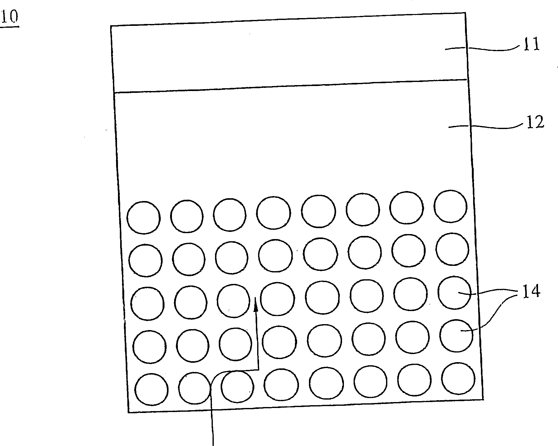
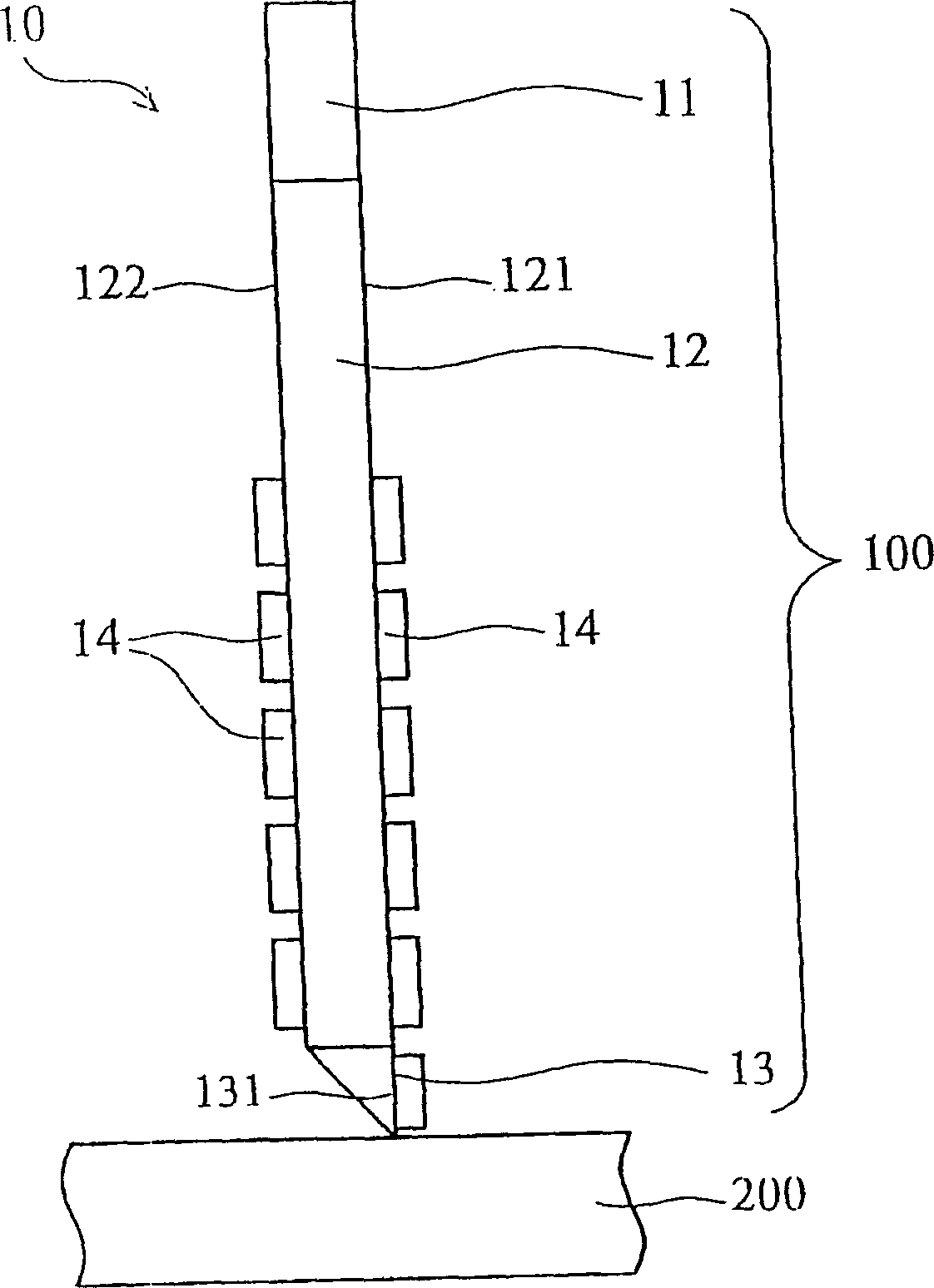
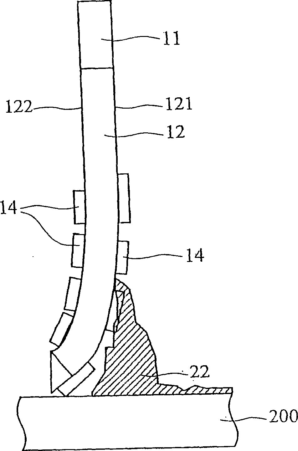
[0050] In order to perform more detailed quantitative analysis on the pollutants in the liquid crystal, the present invention provides a liquid crystal cell panel pollution measurement method and a sampling tool. Such as figure 1 , 2a As shown in and 2b, the present invention extracts the liquid crystal 22 containing pollutants on the panel 200 through the sampling tool 10, and measures the concentration and composition of the pollutants in the liquid crystal 22 through the liquid crystal cell panel contamination measurement method of the present invention without being detected The edge of the panel 200 affects the accuracy of sampling contamination, especially the closer to the edge of the panel the liquid crystal 22 has a higher contamination concentration. Common liquid crystal contaminants include metal ions such as Na + , so sampling must be done to know Na + concentration, the sampling tool of the present invention will be described in detail below.

[0051] Such as...


PUM


Abstract

A method for detecting the pollution of LCD cell plate comprises the following steps: (a) to provide LCD cell plate; (b) to get LCD sample from the plate by use of sample tools; (c) to wash the LCD sample from the tool by use of solvent; (d) to analysis the components of LCD sample ; and (e) to calculate the component concentration to judge whether the plate is polluted.

Description

technical field [0001] The invention relates to a liquid crystal pollution detection method and a sampling tool thereof, in particular to a liquid crystal sampling method using a sampling tool. Background technique [0002] At present, liquid crystal display technology is widely used in general electronic products, such as calculators, electronic watches, mobile phone screens, instruments used in hospitals or screens on digital cameras, etc., liquid crystal displays are based on liquid crystal materials. Because liquid crystal is between solid state and liquid state, it has both liquid and crystalline properties within a certain temperature range, and because of its unique state, it was later named "Liquid Crystal", which is a liquid crystalline substance the meaning of. Therefore, liquid crystal not only has the optical characteristics of solid crystal, but also has the characteristic of liquid flow. The liquid crystal molecules will be affected by the voltage, change the ...

Claims


Application Information

Patent Timeline
IPC IPC(8): G01N1/28G01N33/00G02F1/13
Inventor 黄教忠
Owner AU OPTRONICS CORP
Why Eureka
Try Eureka