Luminous source structure for flat display

A flat-panel display and light source technology, applied in optics, instruments, nonlinear optics, etc., can solve problems such as shortening the service life of liquid crystal displays and increasing production costs

Inactive Publication Date: 2005-01-19
TPO DISPLAY
View PDF0 Cites 3 Cited by
  • Summary
  • Abstract
  • Description
  • Claims
  • Application Information

AI Technical Summary

Problems solved by technology

Considering the conditions of luminous efficiency, service life, etc., only white light-emitting diodes made by NICHIA can be used at present. However, light-emitting diodes that produce white light are cheaper than light-emitting diodes that produce red, green, and yellow light in terms of lifespan and price. Diode differential, which will shorten the life of the LCD display and increase production costs

Method used


Image

  • Luminous source structure for flat display
  • Luminous source structure for flat display
  • Luminous source structure for flat display

Examples


Embodiment Construction

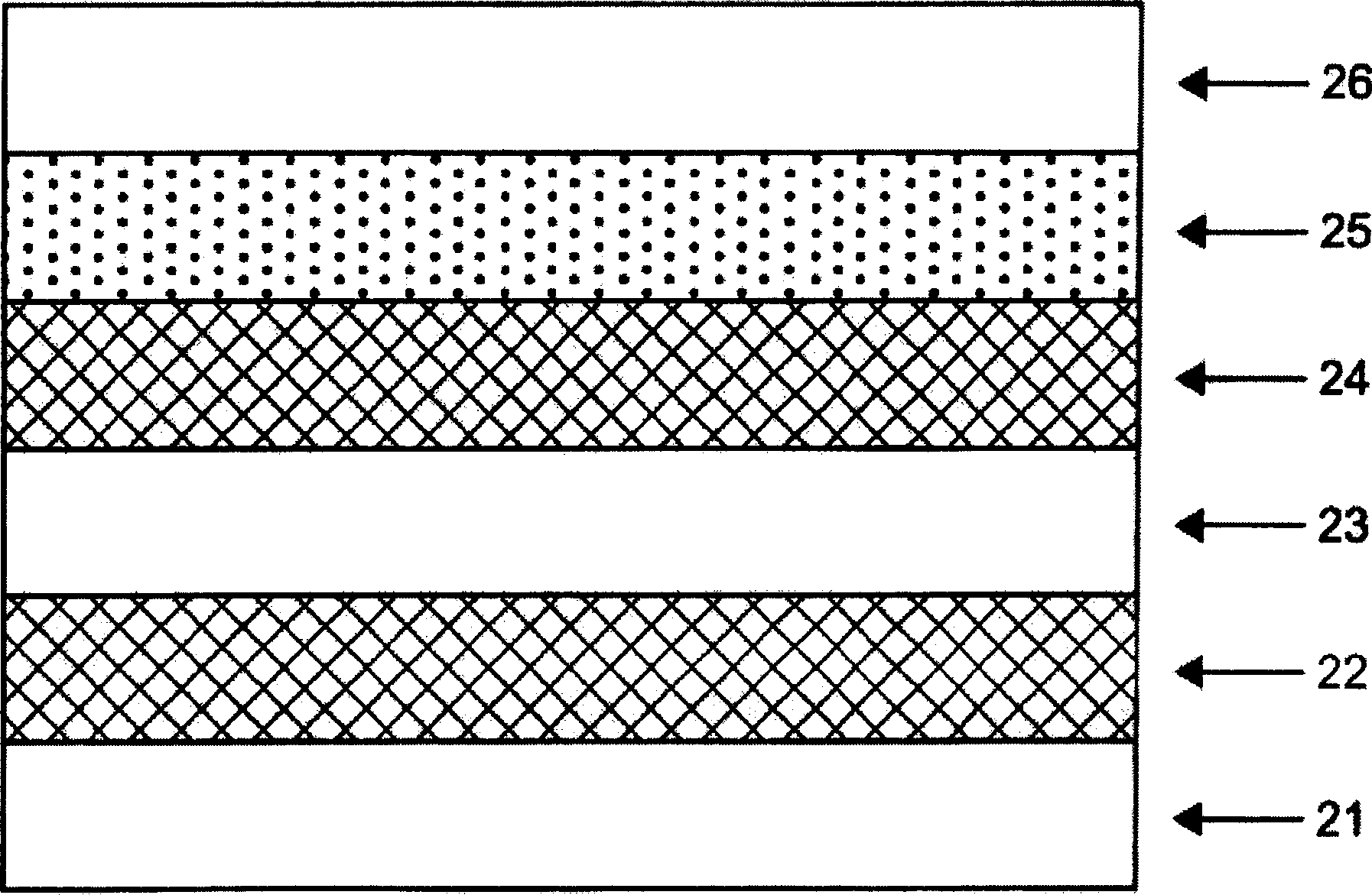
[0024] see Figure 4 , which is a structural schematic diagram of the flat panel display light source in the first preferred embodiment of the present application. Such as Figure 4 As shown, the flat panel display light source structure of the present invention includes a backlight module 40 and a polarizing plate 41, wherein the backlight module 40 is except that the light emitting source 401 is a light emitting diode that produces non-white light, and other components such as a light guide plate, a reflection sheet, and a diffusion sheet Components such as the brightness enhancement sheet and the rhombic sheet are the same as those of the prior art, and will not be repeated here. In addition, except that the polarizer 41 includes one or more fluorescent layers, its material layers such as the surface protection layer 411, the protection layer 412, the polarizer layer 413, the protection layer 414 and the adhesive layer 415 are all the same as those of the prior art. I won...


PUM


Abstract

This invention is a plane display light source structure, which at least comprises: an aphototropism module with a light source to generate first color light, and a deflecting plate with at least one fluorescent layer which is triggered by first color light to generate white light or second color mixed light.

Description

technical field [0001] The invention relates to a light source structure, in particular to a light source structure suitable for flat panel displays. Background technique [0002] With the advent of the information age, flat panel displays have become necessary equipment for various electrical equipment, such as widely used in notebook computers, mobile phones, information appliances (IA) and personal digital assistants (PDA). Lightness, thinness, and power saving are the basic requirements of a display, but limited by issues such as viewing angle, response speed, brightness, and image quality, considerable research and development costs have been invested in related technologies. In the new generation of flat-panel display technology, liquid crystal display has great potential for development due to its characteristics such as high brightness, clear image quality, wide viewing angle, high response speed, and low power consumption. [0003] Please refer to FIG. 1 , which is...

Claims


Application Information

Patent Timeline
Patent Type & Authority Applications(China)
IPC IPC(8): G02B5/30G02F1/13357H01L33/00
Inventor 麦哲魁
Owner TPO DISPLAY
Why Eureka
Try Eureka