Eureka AIR delivers breakthrough ideas for toughest innovation challenges, trusted by R&D personnel around the world.

Amplifying circuit

A technology for amplifying circuits and differential amplifiers, applied in differential amplifiers, DC-coupled DC amplifiers, amplifier input/output impedance improvements, etc., can solve the problems of increased integrated circuit costs and very large circuit area consumption

Inactive Publication Date: 2005-01-19
REALTEK SEMICON CORP
View PDF0 Cites 6 Cited by
  • Summary
  • Abstract
  • Description
  • Claims
  • Application Information

AI Technical Summary

Problems solved by technology

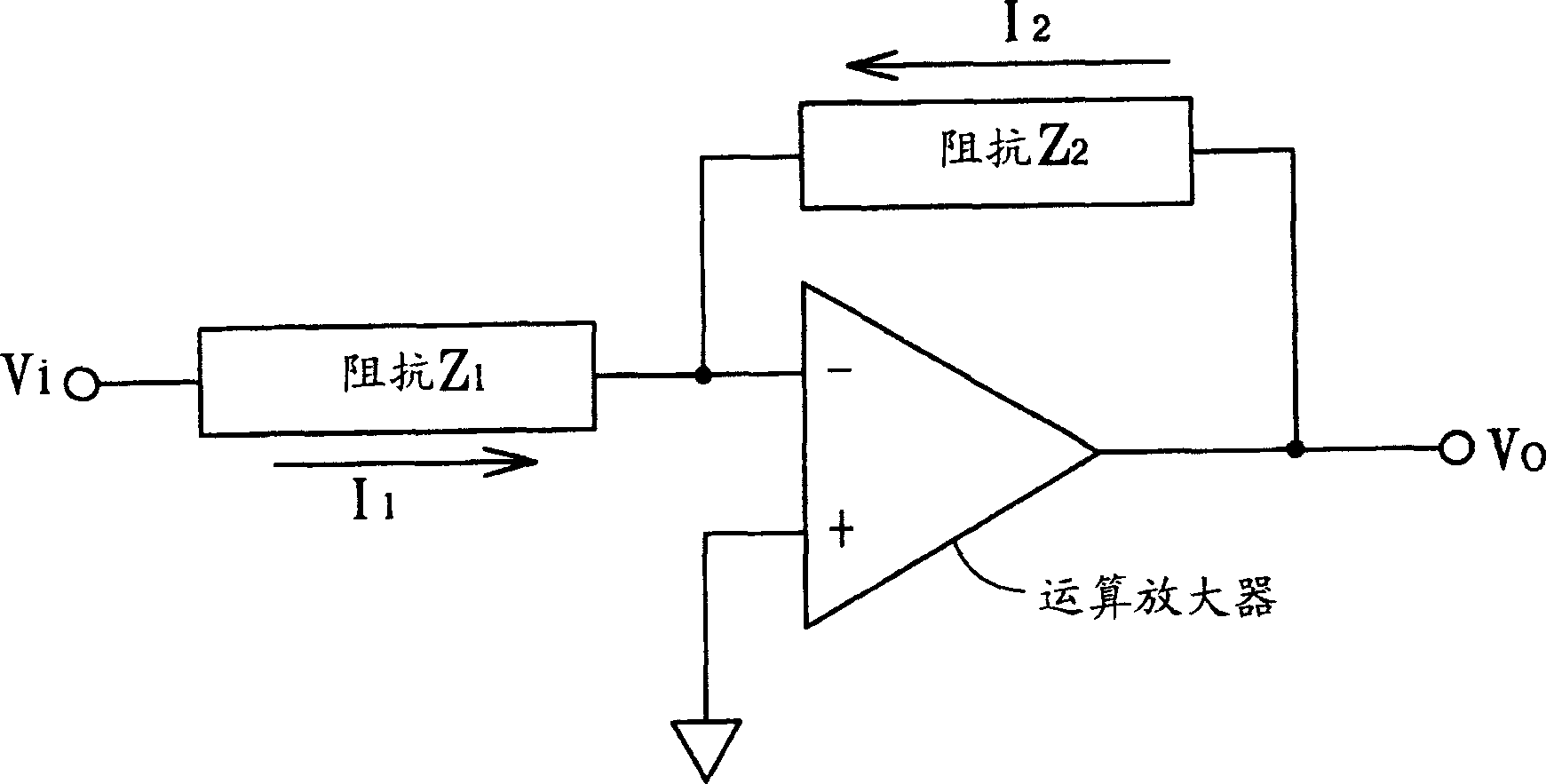
[0007] However, in order to achieve the above-mentioned goals, the above-mentioned various passive components (such as resistors, capacitors, inductors, etc.) need to be of relatively large values, and in the manufacturing process of integrated circuits, it will be very expensive to manufacture passive components with large values. Large circuit area, which will greatly increase the cost of integrated circuit manufacturing

Method used


Image

  • Amplifying circuit
  • Amplifying circuit
  • Amplifying circuit

Examples


Embodiment Construction

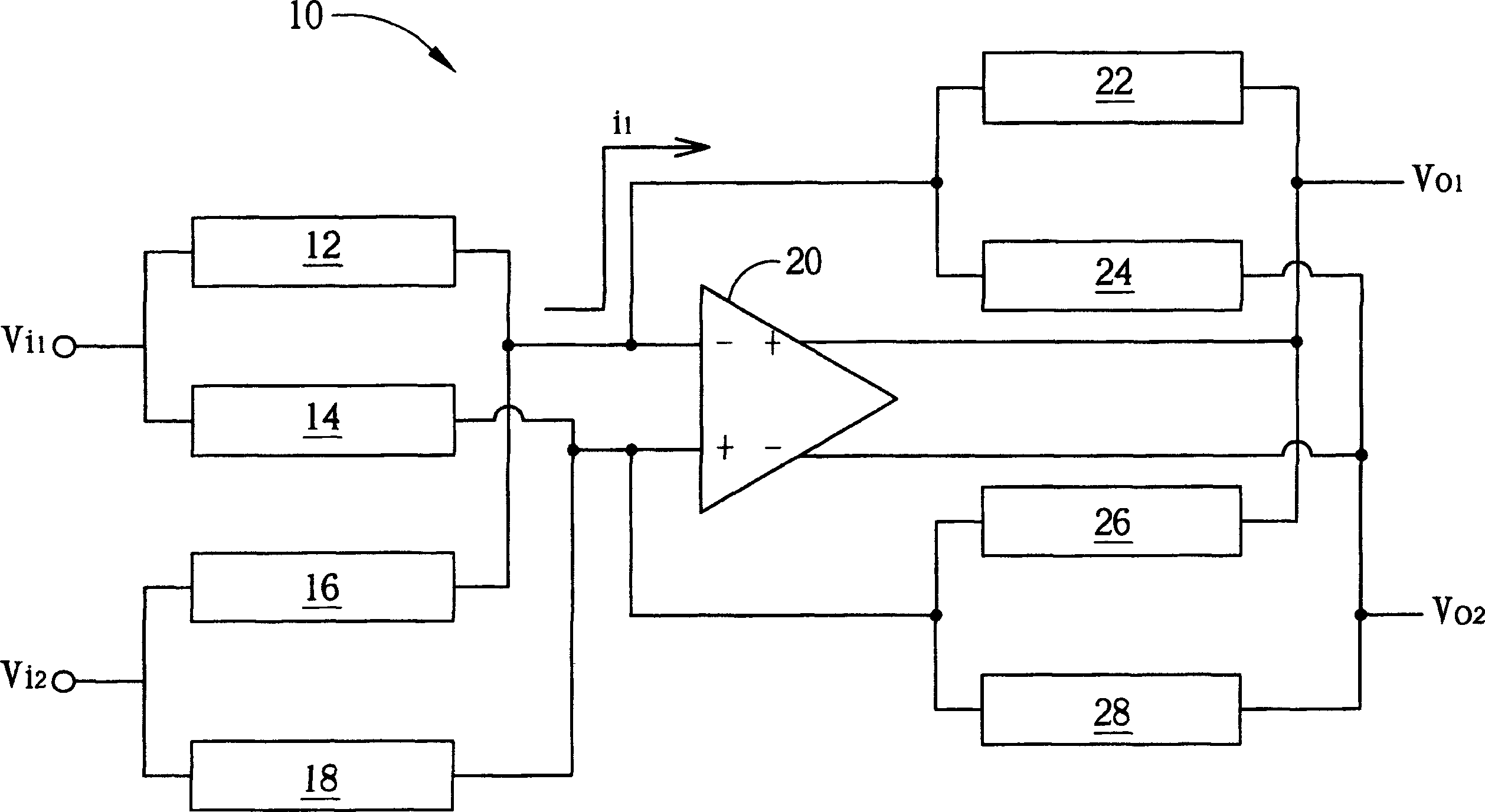
[0032] see figure 2 , figure 2 A schematic diagram of the amplifier circuit 10 of the present invention is shown in . The amplifying circuit 10 includes a differential amplifier 20 with a positive input terminal and a negative input terminal (such as figure 2 +, - signs on the left side of the differential amplifier 20), a positive output terminal, and a negative output terminal (such as figure 2 The + and - sign on the right side of the differential amplifier 20); a first input impedance 12, one end of which is electrically connected to the negative input end, and the other end is electrically connected to a first input signal Vi 1 ; A second input impedance 14, one end of which is electrically connected to the positive input end, and the other end is electrically connected to the first input signal Vi 1 ; A third input impedance 16, one end of which is electrically connected to the negative input end, and the other end is electrically connected to a second input signa...


PUM


Abstract

The invention is an amplifying circuit, containing an amplifier which has a positive input end, a negative end, a positive output end and a negative output end; a first input impedance connected between the negative input end and a first input signal; a second input impedance connected between the positive input end and the first input signal; a third input impedance connected between the negative input end and a second input signal; a fourth input impedance connected between the positive input end and the second input signal; a first output impedance connected between the negative input end and the positive output end; a second output impedance connected between the negative input end and the negative output end; a third output impedance connected between the positive input end and the positive output end; and a fourth output impedance connected between the positive input end and the negative output end.

Description

technical field [0001] The invention provides an amplifying circuit, especially an amplifying circuit which utilizes impedance matching to achieve circuit characteristics such as large equivalent input impedance, large voltage gain value (or large voltage attenuation value), and large time constant. Background technique [0002] Since the invention of the first transistor, human beings have entered the so-called electronic age. With the development of various electronic circuit theories and the rapid development of semiconductor manufacturing technology, circuit design work has become increasingly complex and specialized. In various basic circuit structures, the amplifier circuit has always been a very important part. The amplifier circuit includes functions such as signal amplification and power amplification according to different applications, and the signal amplifier circuit is the most common among them. [0003] see figure 1 , figure 1 A schematic diagram of an ampli...

Claims


Application Information

Patent Timeline
Patent Type & Authority Applications(China)
IPC IPC(8): H03F1/56H03F3/45
Inventor 李朝政张家润
Owner REALTEK SEMICON CORP
Why Eureka
Eureka Blog
Learn More