Equipment for manufacturing steel plastic pipe

A technology for manufacturing equipment and steel-plastic pipes, which is applied in the field of improved steel-plastic pipe manufacturing equipment, can solve the problems of pipe falling and pipe top deviation, and achieve the effect of preventing arching and maintaining normal working conditions.

Inactive Publication Date: 2005-01-26
HANGZHOU TAIXIN IND
View PDF1 Cites 0 Cited by
  • Summary
  • Abstract
  • Description
  • Claims
  • Application Information

AI Technical Summary

Problems solved by technology

figure 1 It is a steel-plastic pipe manufacturing equipment in the prior art. There is a furnace 1 for heating the pipe. One end of the furnace has a rear top cylinder 2, and the other end has a coaxial injection molding machine 3. The injection head 3-1 with a hole extends into the Furnace wall, in the furnace there are several forks 4 that can be lifted and lowered under the axis, and there are pulleys 4-1 at the bottom of the forks to cooperate with the cam mechanism 5 fixed on the outer bottom of the furnace; there is a sprocket device on one side of the furnace, and the outer and The assembly line is matched, and the side is adapted to the horizontal guide rail 18. There is a square base 6 at the bottom of the device, and a sprocket 7 is arranged on the base. The sprocket is connected with spacers 8 at intervals, and the spacer is connected with a concave pad 7-2. Also be provided with the sprocket seat 7-1 of fixing air bag; Air bag 10 comprises air bag seat 10-1, middle air bag body 10-2 and air bag head 10-3, and air bag head has the mouth of accommodating pipe, and air bag seat 10 The gas nozzle 10-1-1 on the -1 is connected with the pressure gas source; there is a matching long bracket 11 on the outer assembly line, and there are a number of rollers 12 on the bracket, and a number of pairs of clamps 13 are fixed to be coaxial with the pipe The long ejector rod 14 is fixed, and the end of the ejector rod is combined with a forming head 15 during work, and there is a cooling water tank 17 near the furnace wall on the outer assembly line, which is characterized in that: but this equipment has the following disadvantages: one is the angle α of the original injection machine head The angle of 60-90° is relatively small, and the pipe is easy to be stuck when the top is withdrawn, which affects its falling with the fork frame 4; the second is that the fork frames of the original 3 injection molding stations are evenly distributed, and the nearest fork frame is far away from the end of the pipe. It is easy to cause the pipe to be deflected; the third is that the sprocket in the sprocket device has an assembly gap because of the existence of the sprocket seat, and the original gas bag positioning point is only one of the sprocket seat. When rotating and working, there will be an arching phenomenon, which will affect the stability of the pipe. ; Fourth, there is no positioning piece before the pipe enters the cooling water tank, and sometimes it will shake

Method used


Image

  • Equipment for manufacturing steel plastic pipe
  • Equipment for manufacturing steel plastic pipe
  • Equipment for manufacturing steel plastic pipe

Examples


Embodiment 1

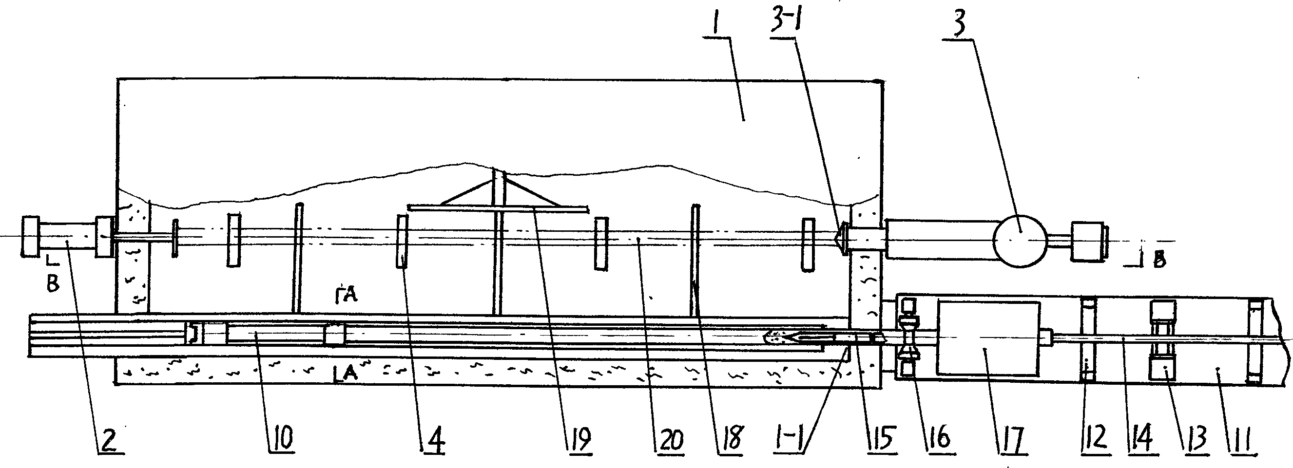
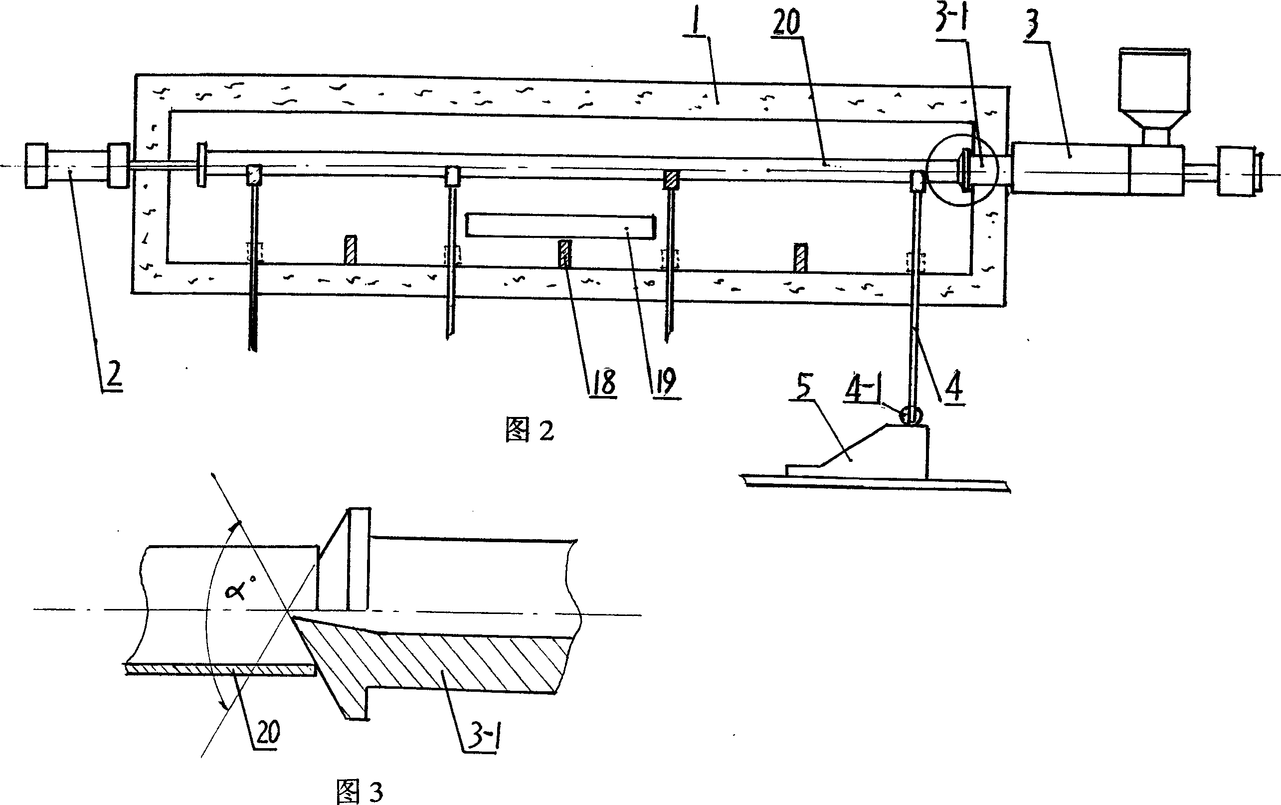
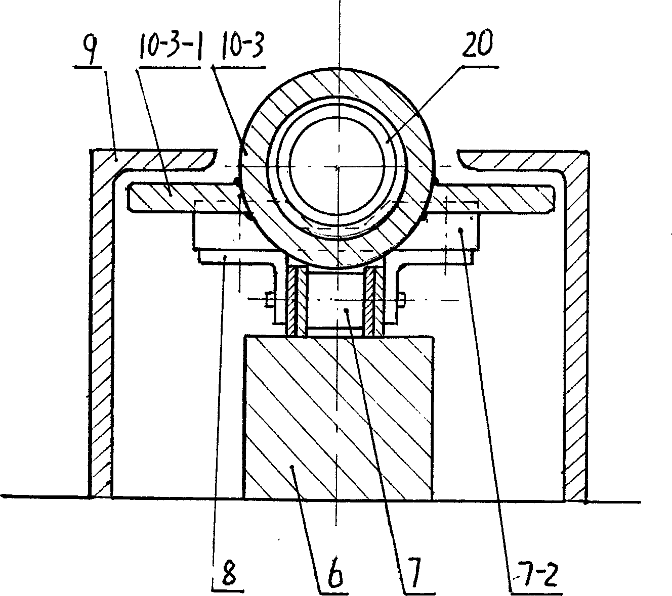
[0017] Example 1. See figure 1 , Figure 2, the steel-plastic pipe manufacturing equipment of this example has a furnace 1 for heating the pipe, 16.2m in length, 1.7m in height and 1.7m in width, one end of the furnace has a rear top cylinder 2, and the other end has a coaxial injection molding machine 3 with holes The head angle of injection machine head 3-1 is 120 ° (seeing Fig. 3) and stretches into furnace wall. Establish four fork frames 4 that can be lifted under the axis, and there are pulleys 4-1 at the bottom of the fork frames to cooperate with the cam mechanism 5 fixed on the outer bottom of the furnace, and the nearest one is 20 cm away from the injection machine head. There is a sprocket device on one side of the furnace, the outside is matched with the assembly line, and the side is adapted to the horizontal guide rail 18. There are symmetrical square guide rails 9 on both sides of the sprocket device. There is a square steel body 6 at the bottom of the device, a...


PUM


Abstract

The invention relates to an improved steel plastic pipe manufacturing device. It includes tube heating, pipe cavity injection moulding, formed pipe covering and cooling part. The character lies in: 1) the angle alpha of injector is 110-120 degrees; 2) the nearest fork bracket has an distance to the injection head less than 50cm; 3) two sides of the chain device has symmetrical set square guide, and air head limited double-ear. Through above mentioned improvement, the injection angle and fork bracket position are distributed reasonably, the chain wheel and the air package eliminate the upwarp phenomenon, the tube state is stable, it can generate out regular steel and plastic pipes.

Description

technical field [0001] The invention relates to a plastic molding equipment, in particular to an improved steel-plastic pipe manufacturing equipment. Background technique [0002] Chinese patent document 99101598.3 discloses a "steel-plastic composite pipe extrusion molding process", which extrudes molten engineering plastics on the inner surface of galvanized steel pipes through special tools to form a dense and firm lining, which is used to manufacture corrosion-resistant steel pipes. Plastic composite pipe. However, this document only discloses the principle of the process, and there is still a distance from the implementation. figure 1 It is a steel-plastic pipe manufacturing equipment in the prior art. There is a furnace 1 for heating the pipe. One end of the furnace has a rear top cylinder 2, and the other end has a coaxial injection molding machine 3. The injection head 3-1 with a hole extends into the Furnace wall, in the furnace there are several forks 4 that can ...

Claims


Application Information

Patent Timeline
Patent Type & Authority Applications(China)
IPC IPC(8): B29C51/16
Inventor 郑耀光
Owner HANGZHOU TAIXIN IND
Why Eureka
Try Eureka