
Micro mirror detecting method and device

A detection method and detection device technology, which are applied to measurement devices, optical devices, laser parts, etc., can solve problems such as consumption, huge time and manpower, and achieve the effect of improving product qualification rate.

Inactive Publication Date: 2005-01-26
BENQ CORP
View PDF0 Cites 3 Cited by
  • Summary
  • Abstract
  • Description
  • Claims
  • Application Information

AI Technical Summary

Problems solved by technology

If the lens is found to be defective after complete assembly, it needs to be disassembled and reassembled, which consumes a lot of time and manpower

Method used


Image

  • Micro mirror detecting method and device
  • Micro mirror detecting method and device
  • Micro mirror detecting method and device

Examples


Embodiment Construction

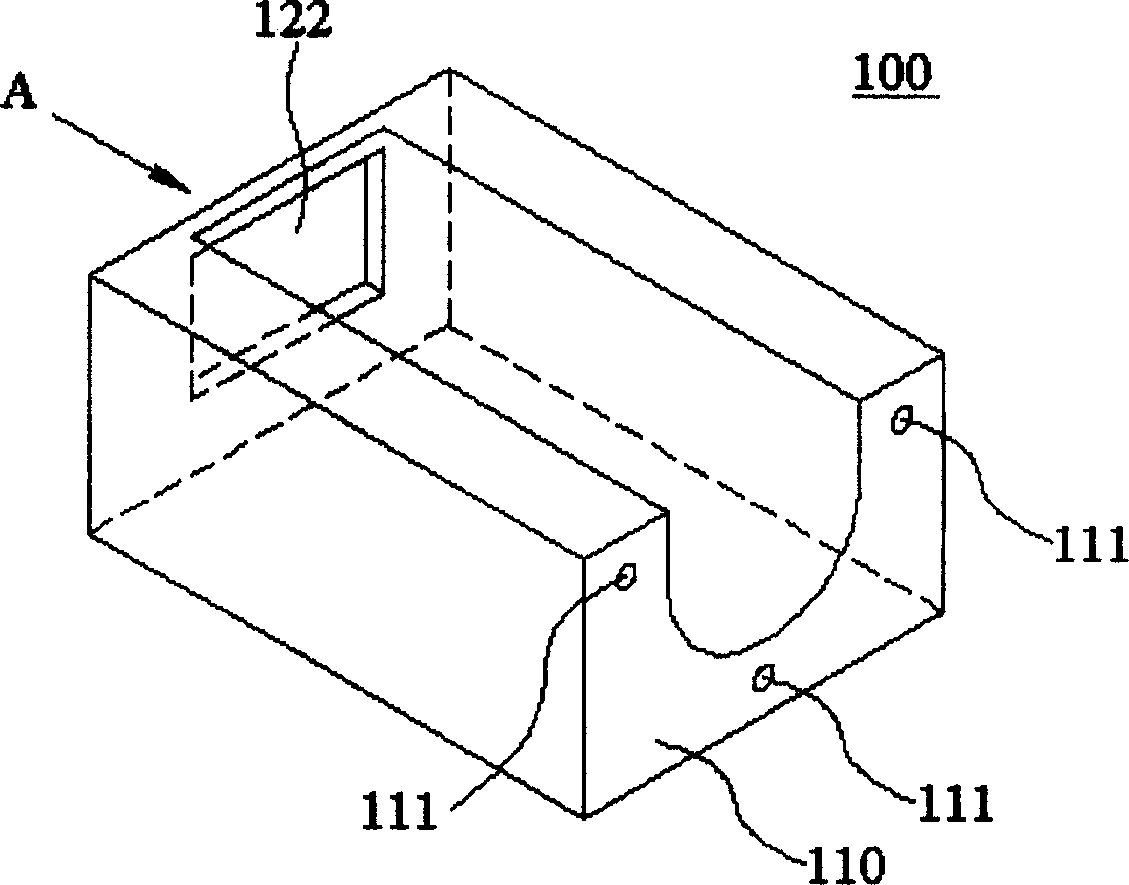
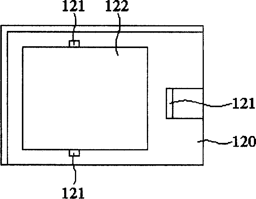
[0014] First, let’s explain the structural reference of the seat Figure 1a , the seat 100 includes a lens supporting surface 110 and a lens supporting point 111 . refer to Figure 1b , which shows the side view of the holder 100 in direction A, the holder 100 also includes a micromirror bearing surface 120 , and the micromirror bearing surface 120 has a micromirror bearing point 121 and an opening 122 . The micromirror assembly is arranged on the micromirror supporting surface 120 by the micromirror supporting point 121 . What the present invention needs to detect is whether the micromirror assembly is excessively tilted when it is installed on the micromirror bearing surface 120 .

[0015] The structure of the micromirror detection device of the present invention will be described below first, and then the micromirror detection method using the micromirror detection device will be described.

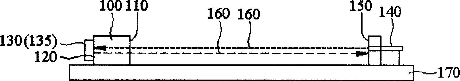
[0016] refer to Figure 2a , the micromirror inspection device of the present i...


PUM


Abstract

This invention relates to a method of microscope measurement. It comprises the following steps: firstly, to set microscope components to the supporting surface; then to let the luminous source ejects light beam which is reflected by the microscope to target surface and get the second light spot; later to measure the distance X between the second light spot and the basic spot and by this to figure out the gradient from the components to the supporting surface.

Description

technical field [0001] The invention relates to a micromirror detection method and a detection device thereof, in particular to a micromirror detection method and a detection device thereof for detecting the inclination of a micromirror assembly after assembly. Background technique [0002] Micro-electro-mechanical technology has been developed for a long time, and it is gradually applied to general daily necessities or electronic products. The digital micromirror component DMD (Digital Micromirror Device) developed by Texas Instruments is a reflective component used in projection equipment. The projector designed by the digital micromirror assembly technology is called a digital light output projector (DLP, Digital Light Processing), which uses the digital micromirror assembly as an imaging device, and reflects light to project an image onto the screen. Its key component, the digital micromirror component, is a semiconductor component developed by Texas Instruments. Each d...

Claims


Application Information

Patent Timeline
IPC IPC(8): G01B11/27H01S5/00
Inventor 郭建峰
Owner BENQ CORP
Learn More