Curved reflector

A curved mirror and spherical mirror technology, applied in the optical field, can solve the problems of increasing the difficulty of subsequent optical path processing and the cost of subsequent optical path processing, and achieve the effects of low cost, improved light efficiency, and high light efficiency

Inactive Publication Date: 2005-01-26
罗筱泠
View PDF0 Cites 5 Cited by
  • Summary
  • Abstract
  • Description
  • Claims
  • Application Information

AI Technical Summary

Problems solved by technology

To improve the uniformity of reflected light, it will inevitably increase the difficulty of subsequent optical path processing in the projection system and the cost of subsequent optical path processing

Method used


Image

  • Curved reflector
  • Curved reflector
  • Curved reflector

Examples


Embodiment Construction

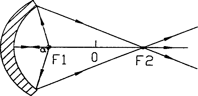
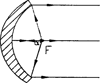
[0041] see image 3 , the curved reflector provided by the present invention is a composite curved reflector, including an ellipsoidal mirror 1 and a spherical mirror 2 . The ellipsoidal mirror 1 is coaxial with the spherical mirror 2 and their inner surfaces are oppositely arranged and combined together to form an irregular ellipsoid.

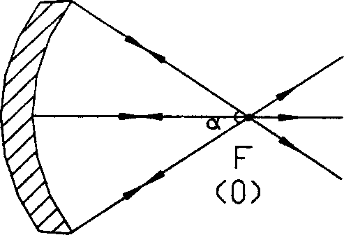
[0042] The ellipsoidal mirror 1 has two focal points F1 and F2, and the spherical mirror 2 has one focal point F. The focal point F of the spherical mirror 2 coincides with the focal point F1 of the ellipsoidal mirror 1 . The light source (not shown in the figure) is arranged at the coincident focus F1 of the ellipsoidal mirror 1 and the spherical mirror 2, that is, the ellipsoidal mirror 1 and the spherical mirror 2 are located on both sides of the light source. With the optical axis as the center, a circular hole 3 is opened on the spherical mirror 2, which serves as a channel for outputting light from the curved reflector.

[0043] The l...


PUM


Abstract

This invention discloses a curved reflecting mirror, which is used to reflect the light from light source in the projection system. The inner surface of the said curved reflecting mirror serves as reflecting surface. The said curved surface comprises non-sphere mirror and sphere mirror, which are in same axis and their inner surfaces, are designed relatively and their focal point overlaps. And the said sphere mirror bottom is opened with a hole as light-out channel. The light source is located on the overlapping focal point. The said invention can increase light effect and prolong service life, and reduce cost and increase reflecting light uniformity.

Description

technical field [0001] The invention relates to the field of optics, in particular to a curved reflector applied in a projection system. Background technique [0002] With the development of projection technology, projection systems are widely used in people's work and study. Currently, the most commonly used optical components in projection systems are internal surface mirrors. The so-called reflector, also known as "reflector", refers to the basic optical element that uses the principle of light reflection to bend the light path in a predetermined direction. The reflectors can be divided into plane reflectors (referred to as flat mirrors) and curved reflectors (referred to as curved mirrors) according to their shape. Curved mirrors can generally be divided into inner surface mirrors and outer surface mirrors according to the position of the reflecting surface. The so-called inner surface reflector can be called "reflective bowl" or "reflective cup". According to common...

Claims


Application Information

Patent Timeline
Patent Type & Authority Applications(China)
IPC IPC(8): G02B5/08G02B5/10
CPCG02B5/10
Inventor 罗筱泠
Owner 罗筱泠
Why Eureka
Try Eureka