

Switch
A switch and moving contact technology, applied in the field of switches, can solve the problems of increased cost, production trouble, cost increase, etc., and achieve the effect of stable operating characteristics and easy production.
- Summary
- Abstract
- Description
- Claims
- Application Information
AI Technical Summary
Problems solved by technology
Method used
Image

Examples
Embodiment Construction
[0042] according to Figure 1 to Figure 24 The accompanying drawings illustrate embodiments of the invention.
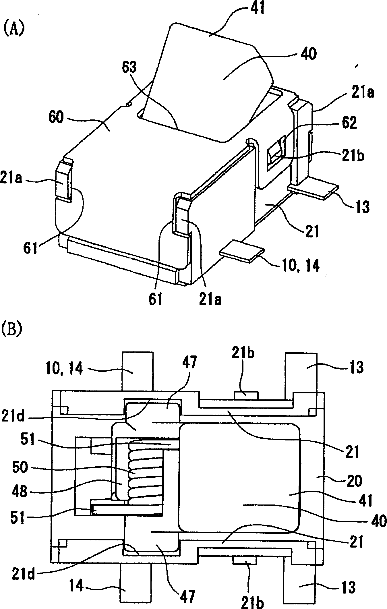
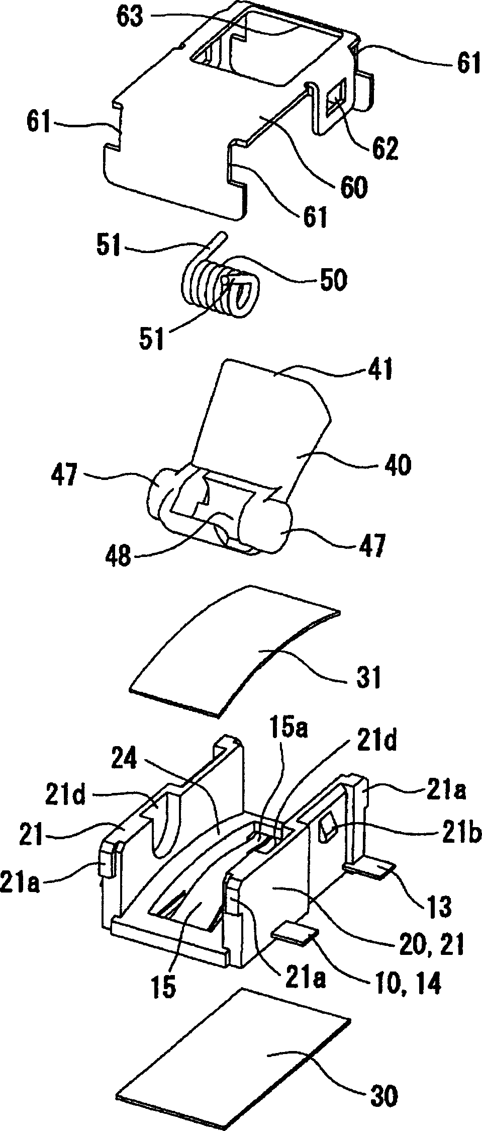
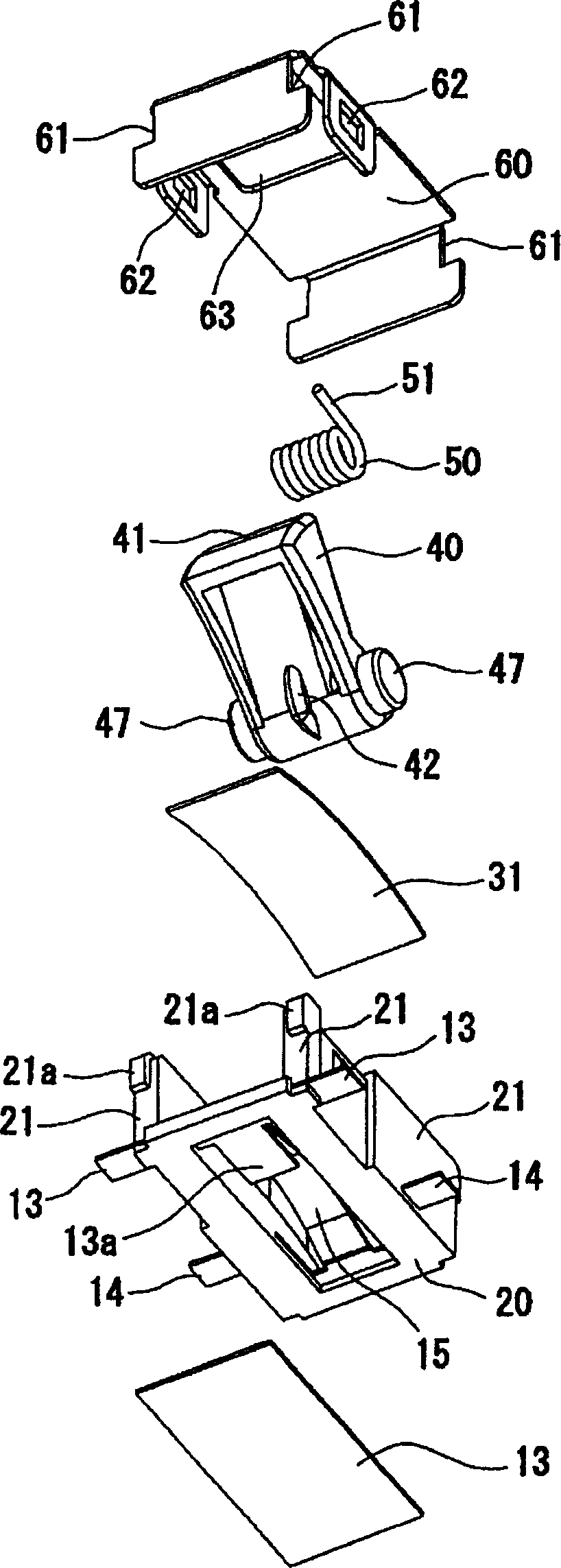
[0043] Such as Figure 1 to Figure 6 As shown, the first embodiment of the present invention includes: a base 20, equipped with a contact mechanism 10 capable of opening and closing a circuit; a lower panel 30 and an upper panel 31, respectively adhered to the upper and lower surfaces of the base 20 to form an integral body; Operating lever 40; return spring 50; cover 60.
[0044] Such as Figure 4 and Figure 5 As shown, the contact mechanism 10 of the base 20 is formed by a lead frame 11 in which the connecting pieces 12 are cut out at a predetermined interval by stamping.
[0045] Promptly cut off a pair of lead wires 13,14 from both sides of the connecting piece 12 ( Figure 4 A). A fixed contact 13a is arranged at the free end of the lead wire 13 on one side, and an auxiliary tongue 13c serving as the lead wire is extended. A movable contact piece 15 is f...
PUM
 Abstract
Description
Claims
Application Information