Method of base station antenna array polarization for wireless system

A base station antenna and wireless system technology, applied in polarization/direction diversity, diversity/multi-antenna systems, antennas, etc., can solve problems such as fewer frequency points, high distribution density of base station antennas, and interference from sending and receiving signals

Inactive Publication Date: 2005-01-26
陆仕海
View PDF0 Cites 7 Cited by
  • Summary
  • Abstract
  • Description
  • Claims
  • Application Information

AI Technical Summary

Problems solved by technology

[0002] At present, wireless communication systems such as mobile and PHS wireless local telephones are widely used in major communication companies. In the application, it is found that there are many radio waves between receiving and transmitting radio frequency base stations with the same frequency. The mobile, PHS wireless local telephone and other systems all use the same polarized radio waves, few frequency points, and the distribution density of bas

Method used


Image

  • Method of base station antenna array polarization for wireless system
  • Method of base station antenna array polarization for wireless system
  • Method of base station antenna array polarization for wireless system

Examples


Embodiment 1

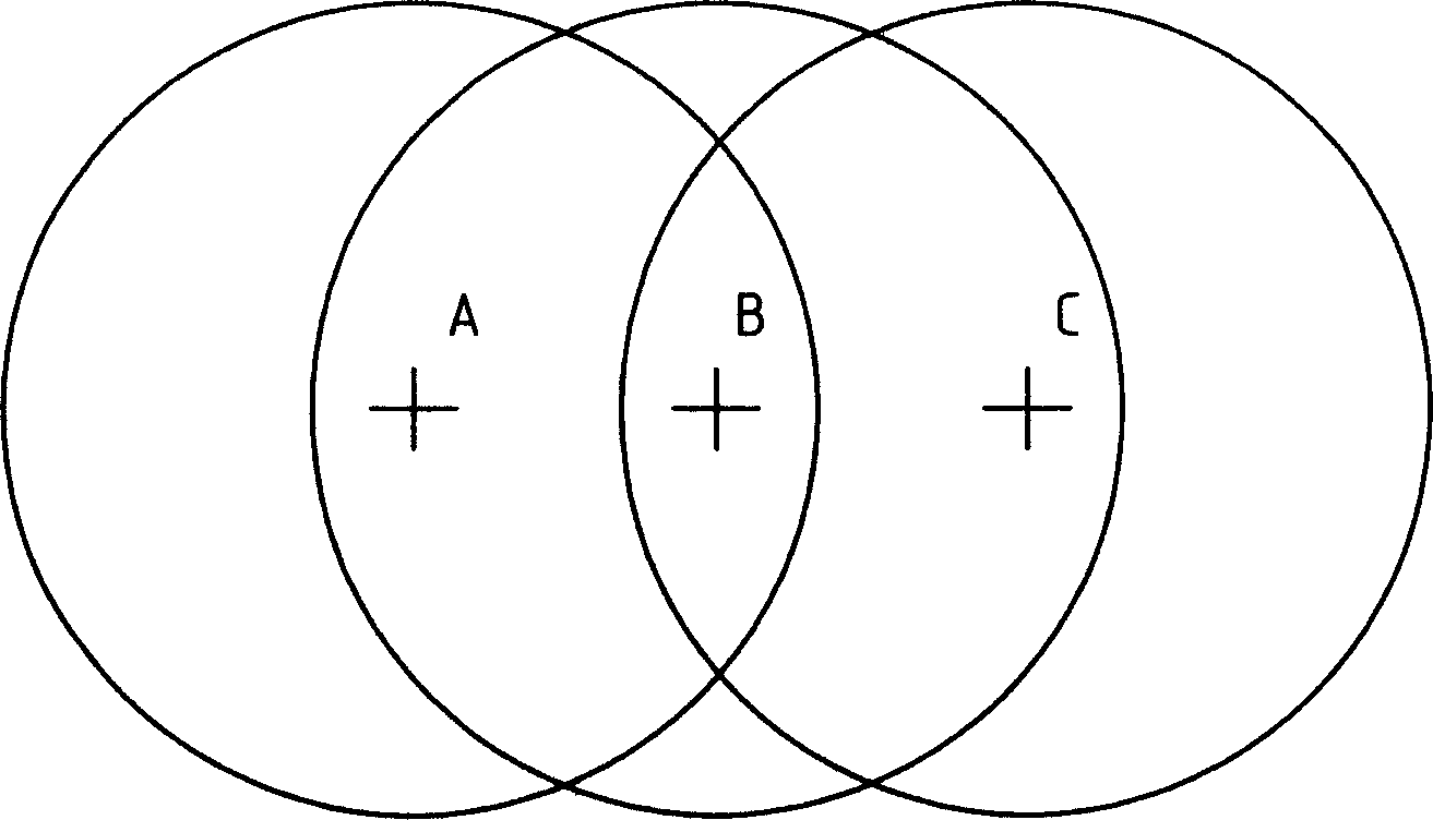
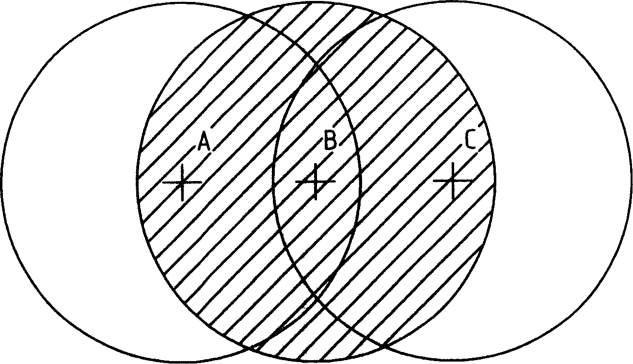
[0024] Reference attached image 3 ,against figure 1 In this arrangement, the antenna that transmits signals from base station B can be changed to an antenna that is polarized differently from the signals received by other base stations. For example, the antenna of base station B can be set to vertical polarization, and the antenna for other base stations to receive signals can be set to vertical polarization. It is horizontal polarization; the antenna of base station B can also be set to horizontal polarization, and the antennas of other base stations receiving signals are set to vertical polarization; in the same way, the antenna of base station A can be set to vertical polarization, B The antenna of the base station receiving signals is set to horizontal polarization; it is also possible to set the antenna of base station A to transmit signals to horizontal polarization, and the antenna of base station B to receive signals to vertical polarization. In this way, the signals rec...

Embodiment 2

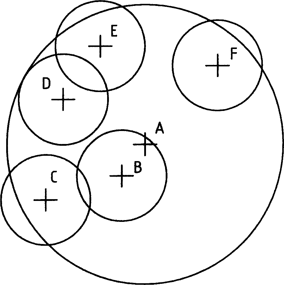
[0026] Reference attached Figure 4 , For attached figure 2 You can change the antenna of base station A to transmit and receive signals to antennas with different polarizations than other base stations to receive and transmit signals. For example, you can set base station A to transmit and receive signals as vertically polarized antennas, and other base stations receive And the transmit signal is set as a horizontally polarized antenna; you can also set the A base station transmit and receive signal as a horizontally polarized antenna, and other base stations receive and transmit signals as a vertically polarized antenna. You can also set A base station transmission to a vertical polarization antenna and receive to a horizontal polarization antenna, other base stations to receive a horizontal polarization antenna, and transmit to a vertical polarization antenna; you can also set A base station transmission to a horizontal polarization Set the vertical polarization antenna and se...

Embodiment 3

[0028] Add base station layout method. This embodiment is a method of adding new base stations on the basis of the original rational layout, such as Figure 5 As shown, A, B, C, D, F, G, H, I, J, K, L, M, N, O are the existing arrangement of the same frequency or adjacent frequency transmission and the other party receiving the same polarization Base station antenna, if you want to add a new base station in the interference area of ​​A, you can choose to place the A1 base station in the area between the A, B, F, and G base stations. This is a better arrangement. A1, A base station radio frequency is the same frequency or adjacent frequency base stations, where A base station transmission is set as a vertical polarization antenna, A1 base station reception is set as a horizontal polarization antenna, A base station reception is set as a vertical polarization antenna, and A1 base station transmission set It is a horizontally polarized antenna; you can set A base station transmission ...


PUM


Abstract

This invention is a system polarization base station antenna anti interference arrangement method that base stations do not communicate with each other but to the third station of a mobile, PHS wireless city call. In the anti interference field that a antennaí»s emission and another í»receive are co-frequency or adjacent frequency, the antennas that emit or receive signals are vertical polarization and horizontal polarization antennas. Stations that may interfere with each other emit different polarized wave, one is vertical polarization and the other is horizontal polarization, and the two waves can not interfere each other, so the interference problem is solved radically. Cell phones can receive horizontal and vertical polarization waves, and cell phones signal can also be received by horizontal and vertical polarization waves. So the utility factor of frequency resources is raised.

Description

Technical field [0001] The patent of the present invention relates to a system that does not perform wireless communication between base stations such as mobile and PHS wireless local calls, but does not perform wireless communication with a third party. The anti-interference arrangement of base station antennas with different radio frequency polarizations in engineering and applications. Background technique [0002] At present, wireless communication systems such as mobile and PHS wireless local calls are widely used in major communication companies. In the application, it is found that there are many radio waves between receiving and transmitting radio frequency co-frequency base stations. There is a problem of transmitting and interfering with receiving. This is because now The mobile and PHS wireless local telephone systems all use the same polarized radio waves, fewer frequency points, and the high density of base station antennas in cities. W...

Claims


Application Information

Patent Timeline
IPC IPC(8): H04B7/10H04W16/00
CPCH04W16/00H04B7/10
Inventor 陆仕海
Owner 陆仕海
Why Eureka
Try Eureka