Metal pliable hose

A flexible and flexible hose technology, applied in the direction of hoses, hose connecting devices, pipes, etc., can solve the problems of reducing corrosion resistance, high cost, and high cost of welding equipment, increasing friction and ensuring tightness , the effect of reducing material cost

Inactive Publication Date: 2005-02-02
FLEXSYS TORA TECH
View PDF0 Cites 1 Cited by
  • Summary
  • Abstract
  • Description
  • Claims
  • Application Information

AI Technical Summary

Problems solved by technology

Image 6 The metal flexible hose of the structure eliminates the problem of the above-mentioned metal mesh falling off. However, the corrugated pipe and the metal mesh are thin-walled pipe body and mesh body made of metal stainless steel. During welding, due to direct heating and simultaneous heating, the part is reduced. In addition, it is necessary to use argon arc welding of shielding gas to weld the bellows all around. While the cost of welding equipment is high, there is also a high requirement for the proficiency of welding operations.
Same with Figure 4 and Figure 5 It is also necessary to use materials with overlapping shapes, and the cost is relatively high

Method used


Image

  • Metal pliable hose
  • Metal pliable hose
  • Metal pliable hose

Examples


Embodiment Construction

[0020] The metal flexible hose of the present invention will be described in detail below in conjunction with examples.

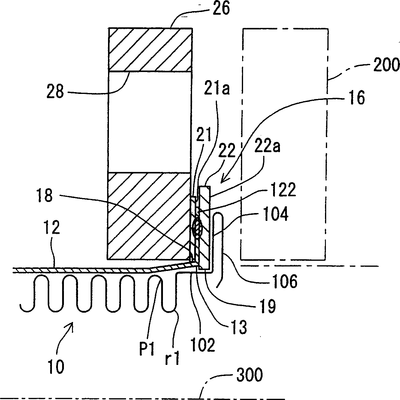
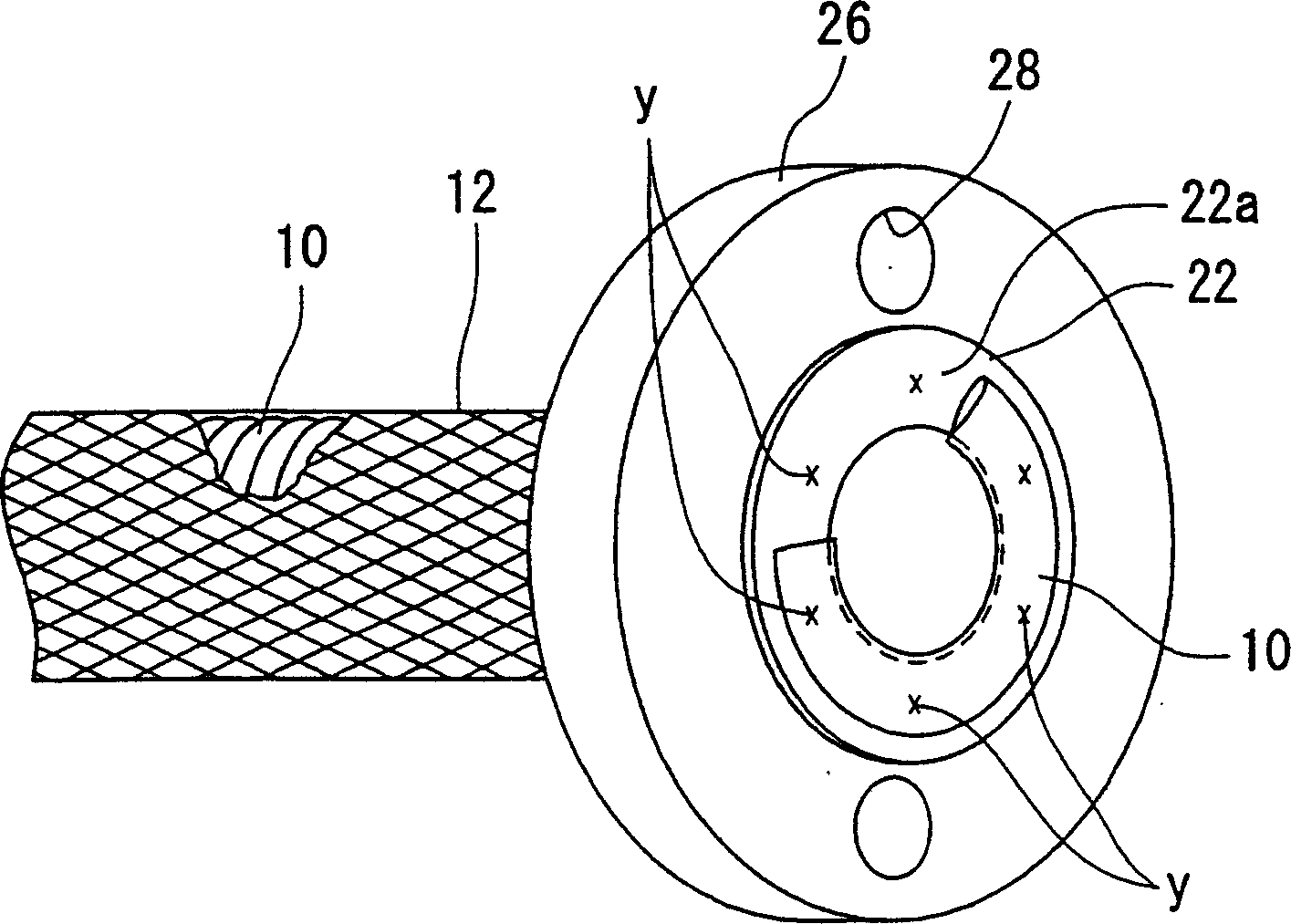
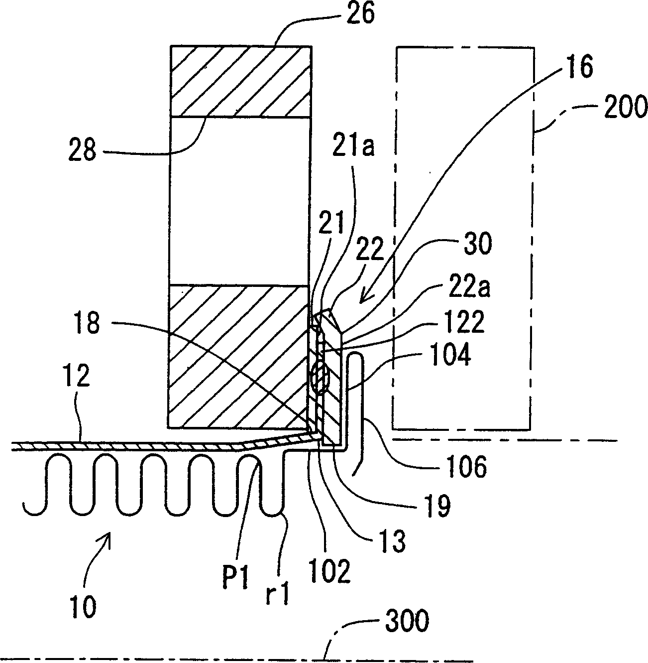
[0021] The structure of the metal flexible hose of the present invention will be described below with an example. Please refer to the attached drawings, and the same symbols will be used for the same components as the original metal flexible hose. figure 1 It is an enlarged explanatory diagram of main parts of the metal flexible hose of Example 1. The metal flexible hose of Example 1 is composed of a bellows 10, a metal mesh 12 covering the bellows, and a metal flexible hose including An integral fixing part 16 including two metal plates 21 and 22 at the ends.

[0022] The corrugated pipe is the same as the original structure. A long stainless steel straight pipe is used as the pipe embryo, and mechanical pressure is applied from the inside or outside of the pipe. At a certain distance, the peak p and the trough r are formed by expanding the drum, repeatin...


PUM


Abstract

Provided is a flexible tube of metal in which coming off of a blade does not occur even in supply of high pressure fluid or under severe usage environments, in which it can be manufactured simply in short time, and in which cost is reduced. At a connection part of a flexible tube of metal to a counter tube, two metal plate members, and an integrated fixture part are provided. The metal plate members have holes 18 and 19 of such diameter that a tube 10 with corrugation can be inserted. The integrated fixture part is provided by holding a terminal of the blade 12 between the two metal plate members, and resistance-welding them to fix them to each other, and it is connected to the counter tube 200 in such a way that plate surfaces 21a and 22a of the metal plate members form a prescribed angle to a lengthwise axial line 300 of the tube 10 with corrugation. By thus welding the blade with the metal plate members to be integrated, and fixing the blade in a bent state, high strength can be maintained to axial force.

Description

technical field [0001] The invention relates to a metal flexible hose, which is used in various pipelines for transporting fluids and has the functions of changing the direction of the pipeline and absorbing the vibration of the pipeline. Background technique [0002] In order to properly change the piping direction and absorb the vibration and thermal expansion and contraction of the piping, metal flexible flexible pipes are used in the upper and lower water pipes, gas transmission pipes, and metal hard pipe piping lines used to transmit power by oil pressure. Tube. The main structure of the metal flexible hose is a hollow cylindrical corrugated tube with mechanically formed crests and troughs interlaced along the length of the tube. The tubes are tightly connected and fixed. The long straight seamed pipe is used as a rough pipe to pressurize from the inside or outside of the pipe, expand and extrude to form a wave peak at every required dist...

Claims


Application Information

Patent Timeline
Patent Type & Authority Applications(China)
IPC IPC(8): F16L33/26F16L11/14
Inventor 白石充儿玉孝典佐佐木生男
Owner FLEXSYS TORA TECH
Why Eureka
Try Eureka