
Double-sided projection exposure device of belt-shape workpieces

A technology for exposure devices and workpieces, which is applied in the direction of photolithography exposure devices, microlithography exposure equipment, electrical components, etc., and can solve problems such as unrealistic, graphic offset, and high cost

Inactive Publication Date: 2005-02-02
USHIO DENKI KK
View PDF2 Cites 11 Cited by
  • Summary
  • Abstract
  • Description
  • Claims
  • Application Information

AI Technical Summary

Problems solved by technology

Since the workpiece is extended during exposure, the workpiece moves relative to the mask image during exposure, and the pattern formed on the workpiece is shifted, and high-precision exposure (replication of mask pattern) cannot be performed.
[0032] It is also considered to use transparent glass to make the work table, but it is difficult to process glass such as quartz that transmits ultraviolet light, which is the exposure light, as a work table that absorbs and holds the work, and it is not practical because the cost is also very high.

Method used


Image

  • Double-sided projection exposure device of belt-shape workpieces
  • Double-sided projection exposure device of belt-shape workpieces
  • Double-sided projection exposure device of belt-shape workpieces

Examples


Embodiment Construction

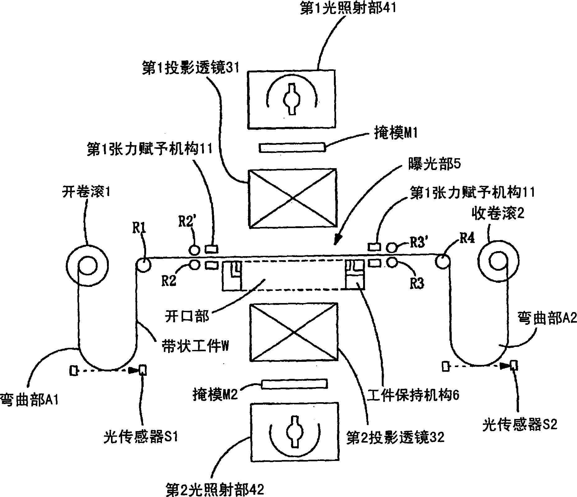
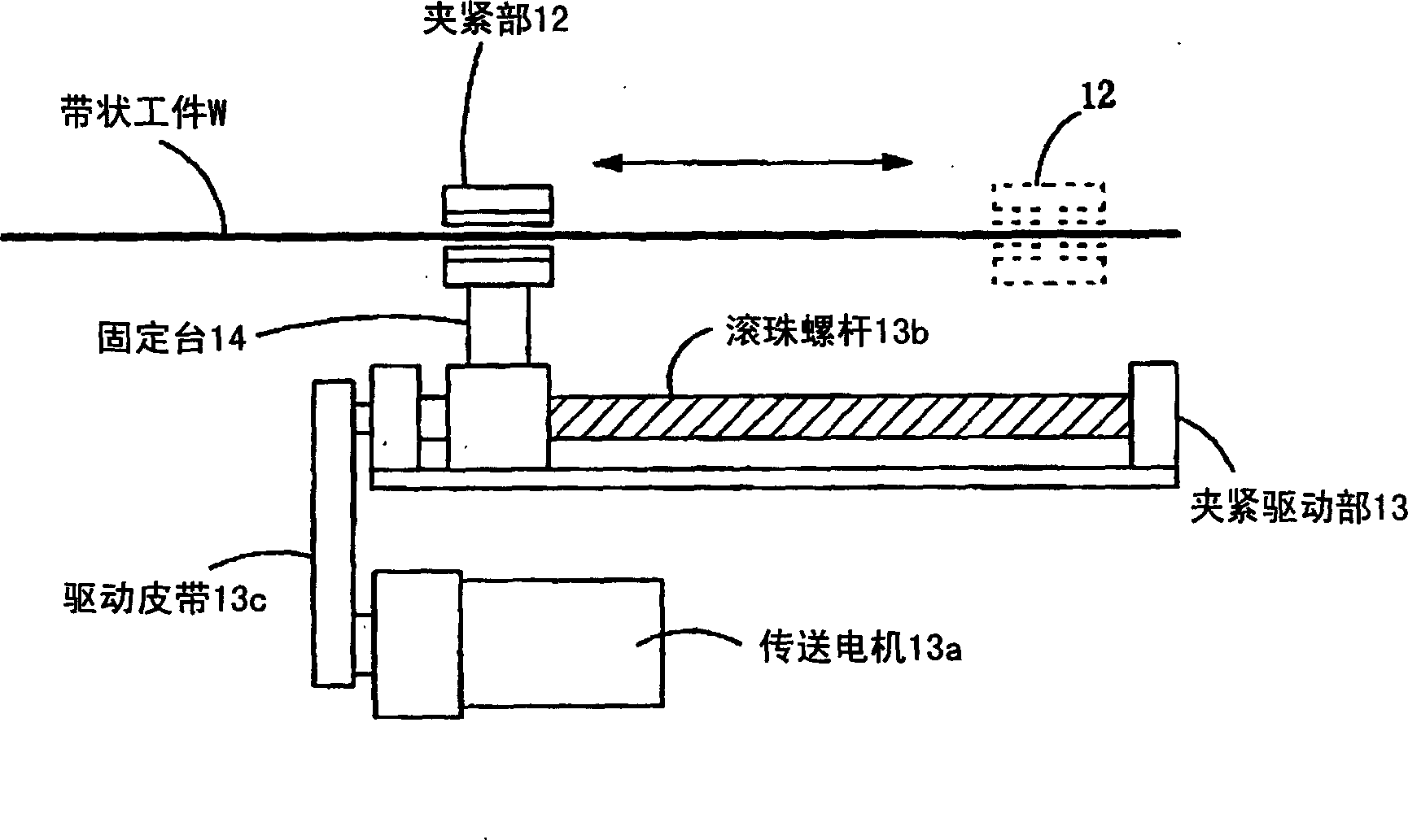
[0056] figure 1 It is a figure which shows the basic structure of the double-sided exposure apparatus of the belt-shaped workpiece which concerns on the Example of this invention. In addition, in figure 1 In , the second mechanism for applying tension in the direction perpendicular to the conveying direction (work width direction) is omitted. In addition, hereinafter, the first and second mechanisms are referred to as first and second tension imparting mechanisms.

[0057] exist figure 1 Among them, a tape-shaped workpiece W such as an FPC (flexible printed circuit board) is wound on an unwinding roll 1 in a roll shape.

[0058] The strip-shaped workpiece W released from the unwinding roller 1 passes through the bending part A1 for adjusting the volume, is turned 90 degrees by the intermediate guide roller R1, passes through the brake roller R2, and is sent into the exposure part 5. The optical sensor S1 is provided in the bending portion A1, and the feeding amount of the ...


PUM


Abstract

Double-sided projection exposure apparatus, to simultaneously expose both faces of a belt-like work for a pattern and to prevent an out-of-focus state or vibration even when the work thermally expands during exposure. The belt-like work W released from a unwinding roll 1 is sent to an exposure section 5, subjected to the tension in the traveling direction and in the direction perpendicular thereto by a first tension imparting means 11 and a second tension imparting means (not shown in the figure) to such a degree to compensate the estimated thermal expansion during exposure, and held with the tension applied by a work holding means 6. A mask M1 and an alignment mark on the top face of the work W, and a mask M2 and an alignment mark on the back face of the work W are detected and aligned. After completing the alignment, the top face and the back face of the belt-like work W are simultaneously exposed by irradiating with exposure light from irradiation parts 41, 42 via the masks M1, M2 and projection lenses 31, 32.

Description

technical field [0001] The present invention relates to an exposure device for exposing both sides of a strip-shaped workpiece, in particular to an exposure device that does not fully absorb and hold the strip-shaped workpiece, and can prevent bending caused by thermal expansion during exposure, and simultaneously exposes both sides of the strip-shaped workpiece exposure device. Background technique [0002] Patterns such as circuits are sometimes formed on both sides of a workpiece such as a printed board, and a double-side exposure device is known as an exposure device used in this process. [0003] For example, in Patent Document 1, a proximity-type double-sided exposure device is described (in this publication figure 1 ). It is described in this document that the substrate (work W) to be exposed is moved to the transfer stage → positioned on the first positioning stage B → exposed on the first exposure stage C → reversed on the inversion stage D The process is perform...

Claims


Application Information

Patent Timeline
IPC IPC(8): G03F7/20H05K3/00
CPCB43K29/093G06C1/00
Inventor 泷浦博文后藤学
Owner USHIO DENKI KK
Learn More