Data transfer apparatus for low voltage differential signaling

A technology for data transmission and differential signals, applied in the field of data transmission equipment for low-voltage differential signals, and can solve the problems of not dealing with common mode noise, increasing the complexity and size of amplifiers, etc.

Inactive Publication Date: 2005-02-02
RENESAS ELECTRONICS CORP
View PDF3 Cites 24 Cited by
  • Summary
  • Abstract
  • Description
  • Claims
  • Application Information

AI Technical Summary

Problems solved by technology

This undesirably increases the complexity and size of the required amplifier
[0012] Yet another disadvantage of the structure shown in FIG. 1 is that it does not handle common mode noise because the coupler 141 is only coupled to one of a pair of signal lines
[0013] These imperfections prevent the desired feedback control of the differential signal amplitude

Method used


Image

  • Data transfer apparatus for low voltage differential signaling
  • Data transfer apparatus for low voltage differential signaling
  • Data transfer apparatus for low voltage differential signaling

Examples


no. 1 example

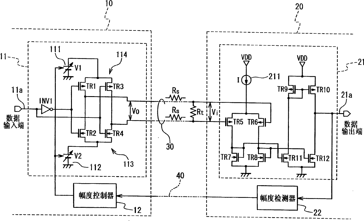
[0038] In the first embodiment shown in FIG. 3 , the data transmission device is composed of a transmitter 10 and a receiver 20 . The transmitter 10 and the receiver 20 are connected by a transmission line 30 comprising a pair of twisted pair signal lines. In addition, a feedback signal line 40 is additionally interposed between the transmitter 10 and the receiver 20 .

[0039] The transmitter 10 includes an output buffer 11 and an amplitude controller 12 . The output buffer 11 generates a differential signal in response to the input transmission data signal 11a. Amplitude controller 12 controls the amplitude of the differential signal generated by output buffer 11 in response to receiving a feedback signal from receiver 20 via feedback signal line 40 .

[0040] The receiver 20 includes an input buffer 21 and an amplitude detector 22 . The input buffer 21 receives the differential signal from the transmitter 10 through the transmission line 30, and converts the received dif...

no. 2 example

[0071] Fig. 7 is a circuit diagram showing the structure of the data transmission device in the second embodiment. The data transmission device in the second embodiment includes a transmitter 10', and the transmitter 10' includes an open-drain output buffer 51 instead of the output buffer 11 shown in FIG. 3 . In addition, the transmitter 10' also includes an amplitude controller 12' which provides the output buffer 51 with a number of amplitude control signals C0 to C2. The output buffer 51 includes first and second drivers 511 and 512, and first and second selectors 513 and 514, which are connected to the first and second drivers 511 and 512, respectively.

[0072]Each driver 511 and 512 is composed of a plurality of n transistors with different driving capabilities, where n is an integer equal to or greater than 2. It should be noted that the term "drive capability" for a particular transistor means the maximum current flowing through the transistor when the transistor is t...


PUM


Abstract

A data transfer apparatus is composed of a transmitter (10) and a receiver (20). The transmitter (10) includes an output buffer developing a differential signal in response to a data signal (11a), and an amplitude controller (12). The receiver (20) includes an input buffer (21) converting the differential signal into a single-end signal (21a), and an amplitude detector (22) developing a feedback signal in response to the single-end signal (21a). The amplitude controller (12) controls an amplitude of the differential signal in response to the feedback signal.

Description

technical field [0001] This invention relates generally to data transmission devices, and more particularly to data transmission devices for low voltage differential signals. Background technique [0002] Low Voltage Differential Signaling (LVDS) is a well known technology for achieving high speed data transmission by reducing Electromagnetic Interference (EMI). To suppress EMI, LVDS-based data transmission devices use differential signals with reduced amplitudes as long as data can be successfully transmitted. [0003] Those skilled in the art know that pre-emphasis, as a technique, can be used to improve the reliability of LVDS data transmission. Japanese laid-open patent application P2002-368600A discloses a pre-emphasis circuit for increasing the amplitude of the edge portion of a differential signal. [0004] Scaling the differential signal is another technique used to improve the reliability of data transmission. LVDS-based data transmission requires proper adjustme...

Claims


Application Information

Patent Timeline
Patent Type & Authority Applications(China)
IPC IPC(8): G06F3/00H03K5/08H03K5/22H04B3/18H04B3/50H04L25/02H04L25/45
CPCH04B17/0067H04B17/24H04L25/45H03K5/086
Inventor 堀良彦中岛启一
Owner RENESAS ELECTRONICS CORP
Why Eureka
Try Eureka